Download
1 / 19
190 likes | 304 Vues
This presentation outlines the development of an RFID chip aimed at meeting the increasing demand for efficient shopping solutions. Led by a team including Idongesit Ebong, Jenna Fu, Bowei Gai, Syed Hussain, and Jonathan Lee, under the guidance of Design Manager Myron Kwai, the project includes key phases such as architectural proposals, Verilog simulations, and advanced layout design. The presentation highlights the current status, discusses design decisions for improved performance, and addresses challenges related to size reduction and signal integrity.

E N D
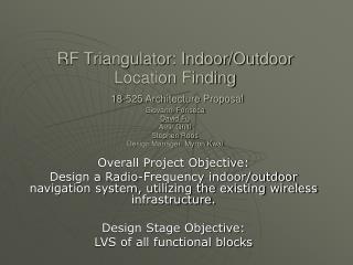
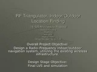
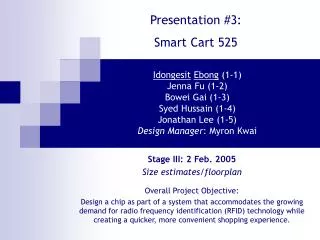
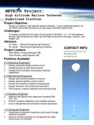
Presentation #9: Smart Cart 525 Idongesit Ebong (1-1)Jenna Fu (1-2)Bowei Gai (1-3)Syed Hussain (1-4)Jonathan Lee (1-5)Design Manager: Myron Kwai Overall Project Objective: Design a chip as part of a system that accommodates the growing demand for radio frequency identification (RFID) technology while creating a quicker, more convenient shopping experience. Stage IX: 16 Mar. 2005 Chip Level Layout
Status • Design Proposal • Project chosen • Verilog obtained/modified • Architecture Proposal • Behavioral Verilog simulated • Size estimates/floorplanning • Gate-level implementation simulated in Verilog • Floorplan and more accurate transistor count • Schematic Design • Component Layout • Functional Block Layout • DRC of functional blocks • LVS of functional blocks • Chip Level Layout (98.56% Done) • 3 Main blocks (each block LVSes) • Full chip LVS • Simulations
Design Decisions • Decided to route more wires over the SBOX and use metal 4 to reach registers on the right • Move items in the encryption block higher up and redesign SBOX logic
Problems & Questions • Registers problematic • How can we make the chip smaller? • Re-doing many of the blocks, learn from previous mistakes. • Reset signal strength and buffer size needed for it. • White space reduction • Simulations take a long time.