Download
1 / 26
270 likes | 469 Vues
Integrated Circuit (IC) or Operational Amplifier (Op-amp) Connections. For Third year Biophysics Special Students. Prepared by: Abdo A. Elfiky. Assistant Lecturer, Biophysics Department, Faculty of Science, Cairo University. Introduction. Integrated circuit (IC), Microcircuit, Microchip,

E N D
Integrated Circuit (IC) or Operational Amplifier (Op-amp) Connections For Third year Biophysics Special Students. Prepared by: Abdo A. Elfiky. Assistant Lecturer, Biophysics Department, Faculty of Science, Cairo University.
Introduction • Integrated circuit (IC), Microcircuit, Microchip, Silicon chip, or Chip) is a small electronic device made out of a semiconductor material. The first integrated circuit was developed in the 1950s. • There are two main advantages of ICs over discrete circuits: cost and performance.
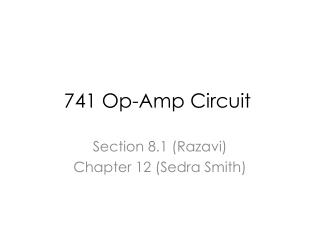
741 type op-amp (1968) IC 741 Biophysics department
Op-Amp positioning on the board IC 741 Biophysics department
Operational amplifier • Op-amps were used to perform mathematical operations such as addition, subtraction,integration,anddifferentiation, hence the term operational. • The op-amp has two input terminals, called the inverting input (-) and the non-inverting input (+), and one output terminal.
Open-Loop Voltage Gain Aol 100,000 volts 1 volt 1 volt
Closed-Loop Voltage Gain Acl • Op-amp can be connected using negative feedback to stabilize the gain and increase frequency response. • Negative feedback takes a portion of the output and applies it back out of phase with the input, creating an effective reduction in gain. This closed-loop gain is usually much less than the open-loop gain and independent of it.
Voltage Follower • Used as a buffer amplifier to eliminate loading effects or to interface impedances (connecting a device with a high source impedance to a device with a low input impedance) -99,999 V 100,000 volts 1 volt
Non-Inverting Amplifier • In a non-inverting op-amp, the input signal is applied to the non-inverting input (+). The output is applied back to the inverting input (-) through the feedback network formed by Ri and Rf . Acl = (Ri+Rf)/ Ri
- 49,999 V 100,000 volts If Rf = Ri = 1KΩ, Then Vf = ½ Vout Acl = 100,000 / 49,999 = ~ 2 1 volt
Inverting Amplifier • In an inverting op-amp, the input signal is applied through a series of input resistor Ri to the inverting input. Also, the output is feedback through Rf to the same input, The non-inverting input is grounded. Acl = -Rf/Ri
- 50,001 V 100,000 volts If Rf = Ri = 1KΩ, Then Vf = ½ Vout Acl = 100,000 / 50,001 = ~ 2 1 volt
Procedure:- Non-inverting connection: • Connect the circuit of the non-inverting op-amp. [ Ri (constant) = 1000 ; Rf (variable) = 0.5K, 1k, 2k, 3k, 5.5k, 8K and 10k)]. • For each value of the Rf find the closed loop gain Acl experimentally (Vout/Vin), and theoretically ((Rf+Ri)/Ri). • Draw a relation between Acl and the values of Rf experimental and theoretical.
Procedure:- Inverting connection: • Connect the circuit of the Inverting op-amp. [ Ri (constant) = 1000 ; Rf (variable) = 0.5K, 1k, 2k, 3k, 5.5k, 8K and 10k)]. • For each value of the Rf find the closed loop gain Acl experimentally (Vout/Vin), and theoretically (–Rf/Ri). • Draw a relation between Acl(experimental and theoretical) and the values of Rf.
Procedure:- • Connect the circuit of the Inverting op-amp. [ Rin1 ,Rin2 are constant = 1000 ; Rf (variable) = 1k, 2k, 3k, 5.5k, and 8K ]. • For each value of the Rf find the output voltage Vout experimentally, and theoretically (–Rf/R(Vin1+Vin2)). • Draw a relation between Vout(experimental and theoretical) and the values of Rf.
Thank you prepared by: Abdo A. Elfiky

![What is an IC ? [integrated circuit]](https://cdn1.slideserve.com/2972450/slide1-dt.jpg)