Chapter 8 – Integrated Circuit Logic Families
1.26k likes | 1.85k Vues
Chapter 8 – Integrated Circuit Logic Families. Chapter 8 Objectives. Selected areas covered in this chapter : Digital IC terminology as in manufacturer data sheets. Characteristics of various TTL series. Characteristics of the various CMOS series.

Chapter 8 – Integrated Circuit Logic Families
E N D
Presentation Transcript
Chapter 8 Objectives • Selected areas covered in this chapter: • Digital IC terminology as in manufacturer data sheets. • Characteristics of various TTL series. • Characteristics of the various CMOS series. • Major characteristics & differences among TTL, ECL, MOS, and CMOS logic families. • Considerations when interfacing digital circuits from different logic families. • Using voltage comparators to allow a digital systemto be controlled by analog signals. • Using a logic pulser and a logic probe as digitalcircuit troubleshooting tools.
Chapter 8 • Digital IC technology has advanced rapidly from integrations which can 1 million or more gates. • ICs pack more circuitry in a small package, so overall size of almost any system is reduced. • Cost is reduced because of the economies ofmass-producing large volumes of similar devices. • ICs have made digital systems more reliable by reducing the number of external interconnections from one device to another. • Protected from poor soldering, breaks or shortsin connecting paths on a circuit board, and otherphysical problems.
Chapter 8 • ICs cannot handle very large currents or voltage. • Heat generated in such small spaces would cause temperatures to rise beyond acceptable limits. • For higher power levels, an interfacing circuit will be needed—typically of components or special power ICs. • ICs can’t easily implement certain devices suchas inductors, transformers, and large capacitors. • Principally used to perform low-power circuit operations—commonly called information processing.
Chapter 8 • Various logic families differ in major componentsin their circuitry. • TTL and ECL use bipolar transistors as their major circuit element. • PMOS, NMOS, and CMOS use unipolar MOSFET transistors.
8-1 Digital IC Terminology IC nomenclature & terminologyis fairly standardized.
8-1 Digital IC Terminology IC nomenclature & terminologyis fairly standardized.
8-1 Digital IC Terminology – Fan Out • A logic-circuit output is generally required to drive several logic inputs. • Sometimes all ICs are from the same logic family. • But many systems have a mix of various logic families. • The fan-out—loading factor—is the maximum number of logic inputs an output can drive reliably.
Propagation delays. 8-1 Digital IC Terminology – Propogation Delay • A logic signal always experiences a delay going through a circuit. • The two propagation delay times are defined as:
8-1 Digital IC Terminology – Power Requirements • Every IC requires a certain amount of electrical power to operate. • Supplied by one or more power-supply voltages connected at VCC(TTL) or VDD (MOS devices). • For many ICs, current drawn from the supply varies depending on logic states of the circuits on the chip.
In some logic circuits, averagecurrent is computed basedon the assumption that gateoutputs are LOW half thetime and HIGH half the time. 8-1 Digital IC Terminology – Power Requirements • The amount of power an IC requires is determined by the current, ICC(or IDD) it draws from the supply. • Actual power is the product ICC x VCC (IDD x VDD ).
can be rewritten to calculateaverage power dissipated: 8-1 Digital IC Terminology – Power Requirements • The amount of power an IC requires is determined by the current, ICC(or IDD) it draws from the supply. • Actual power is the product ICC x VCC (IDD x VDD ).
8-1 Digital IC Terminology – Noise • Stray electric/magnetic fields can induce voltages on the connecting wires between logic circuits • Called noise, these unwanted, spurious signals can sometimes cause unpredictable operation.
High-state noise margin: Low-state noise margin: 8-1 Digital IC Terminology – Noise • Noise immunity refers to the circuit’s ability to tolerate noise without changes in output voltage. • A quantitative measure is called noise margin.
8-1 Digital IC Terminology – Invalid Voltage • For proper operation, logic circuit input voltage levels must be kept out of the indeterminate range. • Lower than VIL(max) or higher than VIH (min). • Invalid voltage will produce unpredictable output. • It is important to know valid voltage ranges for the logic family being used so invalid conditions can be recognized when testing or troubleshooting. • Logic families can be described by how current flows between the output of one logic circuit and the input of another.
8-1 Digital IC Terminology – Current Sourcing/Sinking • Current-sourcing action. • When the output of gate 1 is HIGH, it suppliescurrent IIH to the input of gate 2. • Which acts essentially as a resistance to ground. • The output of gate 1 is acting as a source ofcurrent for the gate 2 input.
8-1 Digital IC Terminology – Current Sourcing/Sinking • Current-sinking action. • Input circuitry of gate 2 is represented as a resistance tied to +VCC—the positive terminal of a power supply. • When gate 1 output goes LOW, current will flow from the input circuit of gate 2 back through the output resistance of gate 1, to ground. • Circuit output that drives the input of gate 2 must be able to sink a current, IIL , coming from that input.
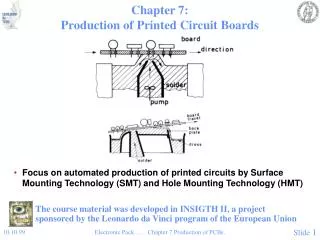
The DIP (dual-in-line package)has pins (leads) down thetwo long sides of therectangular package. The notch on one end,is used to locate pin 1. Some DIPs use a smalldot to locate pin 1. 8-1 Digital IC Terminology – IC Packages • There are many IC packages, differing inphysical size, environmental & power consumption conditions, and circuit board mounting
Held in place by a solder paste,and the entire board is heated tocreate a soldered connection. Precision machine placementallows for very tight lead spacing. Leads are bent out from the plastic case, providing adequate surfacearea for the solder joint. 8-1 Digital IC Terminology – IC Packages • Current manufacturing methods use surface-mount technology (SMT), which places an IConto conductive pads on the surface of the board.
The PLCC has J-shapedleads that curl under the IC. These devices can be surface-mounted to a circuit board—but canalso be placed in a special socket. Commonly used for componentslikely to need to be replacedfor repair or upgrade. 8-1 Digital IC Terminology – IC Packages • Need for more connections to a complex IC has resulted in another very popular package withpins on all four sides of the chip.
QFP and TQFP packageshave pins on all four sidesin a gull-wing surface-mount package. 8-1 Digital IC Terminology – IC Packages • Need for more connections to a complex IC has resulted in another very popular package withpins on all four sides of the chip.
The pin grid array (PGA) is a similar package, use when components must be in asocket to allow easy removal. The PGA has a long pin instead of a contact ball (BGA) at each position in the grid. 8-1 Digital IC Terminology – IC Packages • The ball grid array (BGA) shown in is a surface-mount package that offers even more density.
8-1 Digital IC Terminology – IC Packages • The land grid array (LGA)package is essentially aBGA package without thesolder balls attached.
Logic gates are available in individual surface-mount packages containingone, two, or three gates, and as fewas five or six pins (power, ground,two to three inputs, and an output) 8-1 Digital IC Terminology – IC Packages
8-2 The TTL Logic Family • Most TTL circuits have a similar structure • NAND and AND gates use multiple-emitter transistor or multiple diode junction inputs. • NOR and OR gates use separate input transistors. • The input will be the cathode of a P-N junction • A HIGH input will turn off the junction. • Only a leakage current is generated. • A LOW input turns on the junction. • Relatively large current is generated. • Most TTL circuits have some type of totem-pole output configuration.
Basic TTLNAND gate. 8-2 The TTL Logic Family The basic TTL logic circuit is the NAND gate. Diode equivalent for Q1 .
8-2 The TTL Logic Family TTL NAND gate LOW output
8-2 The TTL Logic Family • A TTL output acts as a current sink in the LOW state because it receives current from the input of the gate that it is driving. Transistor Q4 of the driving gate is on and essentially “shorts” point X to ground. LOW voltage at X forward-biases the emitter–base junction of Q1 & currentflows back through Q4.
8-2 The TTL Logic Family • A TTL output acts as a current sink in the LOW state because it receives current from the input of the gate that it is driving. Q4 is performing a current-sinking action—deriving its current from the inputcurrent (IIL) of the load gate. Q4 is often called the current-sinking transistor or pull-down transistor becauseit brings the output voltage down to its LOW state.
8-2 The TTL Logic Family TTL NAND gate HIGH output
8-2 The TTL Logic Family • A TTL output acts as a current source in the HIGH state—a small reverse-bias leakage current. Transistor Q3 is supplying the input current (IIH) requiredby Q1 of the load gate. Q3 is often called the current-sourcing or pull-up transistor.In more modern TTL series,the pull-up circuit is madeup of two transistors.
The NOR circuit does not use amultiple-emittertransistor.Each input is applied tothe emitter of a separate transistor. The NOR circuit usesthe same totem-pole arrangement as the NAND circuit on the output side 8-2 The TTL Logic Family Internal circuit for a TTL NOR gate.
8-3 TTL Data Sheets • The first line of TTL ICs was the 54/74 series from Texas Instruments—introduced in 1964. • Manufacturers use the same numbering system. • Prefix indicates manufacturer. • SN – Texas Instruments. • DM – National Semiconductor. • S – Signetics. • DM7402, SN7402, S7402 perform the same function. • Data sheets contain electrical characteristics, switching characteristics, and recommended operating conditions.
8-3 TTL Data Sheets Data sheet for the 74ALS00 NAND gate IC
74ALS series voltage levels. 8-3 TTL Data Sheets Data sheet for the 74ALS00 NAND gate IC
8-4 TTL Series Characteristics Typical TTL series characteristics.
8-5 TTL Loading and Fan-Out • Fan-out refers to the load drive capability of anIC output • A TTL output has a limit on how much current it can sink in the LOW state, or source in the HIGH state. • Exceeding these currents will result in output voltage levels outside specified ranges. • Determining fan out • Add the IIH for all inputs connected to an output. • Sum must be less than the output IOH specification. • Add the IIL for all inputs connected to an output. • Sum must be less than the output IOL specification.
8-5 TTL Loading and Fan Out Currents when a TTL output is driving several inputs.
8-6 Other TTL Characteristics • Unconnected (floating) inputs. • On any TTL IC, all of the inputs are 1s if they arenot connected to some logic signal. • An input left unconnected, it is said to be floating.
Three ways to handle unused logic inputs. 8-6 Other TTL Characteristics – Unused Inputs • Frequently, not all inputs on a TTL IC are being used in a particular application. • A common example is when not all the inputs to a logic gate are needed for the required logic function. • Unused input can be connected to +5V through a1k-Ohm resistor, so the logic level is a 1. • A third possibility is where the unused input is tiedto a used input.
8-6 Other TTL Characteristics – Tied-Together Inputs • Two (or more) TTL inputs on the same gate connected to form a common input will generally represent a load that is the sum of the loadcurrent rating of each individual input. • The only exception is for NAND and AND gates. • The LOW-state input load will be the same as asingle input—no matter how many inputs are tied together.
Resistor R keepsthe T input LOWwhile the switchis open. 8-6 Other TTL Characteristics – Biasing TTL Inputs LOW • Occasionally a TTL input must be held normally LOW and caused to go HIGH by actuation of a mechanical switch. • The one-shot triggers on a positive transition that occurs when the switch is momentarily closed.
8-6 Other TTL Characteristics – Current Transients • TTL logic circuits suffer from internally generated current transients or spikes due to the totem-pole output structure. Ceramic disk capacitors (.01 or.1 F) are used to short thesehigh frequency spikes to ground.
The electric field on the metal electrode side of the oxide insulator has an effect on the resistance of the substrate. 8-7 MOS Technology • MOS technology derives its name from the basic structure of a metal electrode, over an oxide insulator, over a semi-conductor substrate. • Transistors of MOS technology are field-effecttransistors—called MOSFETs. • Most of the MOS digital ICs are constructed entirely of MOSFETs and no other components. • MOSFETs are relatively simple and inexpensiveto fabricate, small, and consume very little power.
8-7 MOS Technology • The principal disadvantage of MOS devices is their susceptibility to static-electricity damage. • Although minimized by proper handling, TTL isstill more durable for laboratory experimentation.
The direction of the arrow indicates either P- or N-channel. The symbols show a broken line between the source and the drain to indicate thereis normally no conducting channel between these electrodes. 8-7 MOS Technology • There are presently two general types of MOSFETs—depletion and enhancement. • MOS ICs use enhancement MOSFETs exclusively.
8-7 MOS Technology – Basic MOSFET Switch • An N-channel MOSFET is the basic element in a family of devices known as N-MOS. • Drain is always biased positive relative to the source.
8-7 MOS Technology – Basic MOSFET Switch • Gate-to-source voltage VGSis the input voltage. • Used to control resistance between drain & source. • Determines whether the device is on or off.
8-7 MOS Technology – Basic MOSFET Switch • The P-channel MOSFET—P-MOS—operates in the same manner as the N-channel. • Except that it uses voltages of opposite polarity. • The drain is connected to the lower side of the circuit so it is biased with a more negativevoltage relative to the source.