CTL Redundancy
CTL Redundancy. Meeting 03-Jun-2009 (updated June 22). col 0. col 255. col 256. col511. Block (L). control. Block (R). Words : 1024 Width : 32 ColMux : 16. Q[31:0]. A[9:0]. repair columns. D[31:0]. FAL[5:0]. FEL. FAR[5:0]. FER. Memory I/f. Memory Example - 1. bit map.

CTL Redundancy
E N D
Presentation Transcript
CTL Redundancy Meeting 03-Jun-2009 (updated June 22)
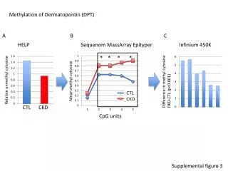
col 0 col 255 col 256 col511 Block (L) control Block (R) Words : 1024 Width : 32 ColMux : 16 Q[31:0] A[9:0] repair columns D[31:0] FAL[5:0] FEL FAR[5:0] FER Memory I/f Memory Example - 1 bit map Description columns are divided into groups of 4. There may be a maximum of 512 columns per side – giving 128 column sets of four. The address of the column set containing the column to be repaired is programmed into the fuse latches – along with the column enable fuse data. Note that the 0th column set of 4 columns is the one lying closest to the middle of the memory. Hence, for blocks on the left hand side, column set 0 will correspond to the 128th physical set of columns – starting from the leftmost edge of the memory. For the right hand side, column set 0 is physically the closest set of 4 columns to the center of the memory – or physically the 129th column set counting from the leftmost edge. This repair scheme allows for independent column repair for each side of the memory.
failDataMap proposal DataConnectivity { rapairAddressBus[range] = failDataMap { //IO to be repaired : repair value D[range] : Value / CTL Function } // Value in repairAddressBus for no repair or value to be specified for unused repair element’s control Default : Value } DataConnectivity { FAL[1:0] = failDataMap { //This representation allows arbitrary mapping for repair data D[3] : 2’b11 D[2] : 2’b10 D[1] : 2’b01 D[0] : 2’b00 } Default : xx } DataConnectivity { FAL[1:0] = failDataMap { //Simpler representation for generic binary encoding // Bin (range) returns a list of binary encoded value for the decimal range specified and maps one-to-one for IO range specified in LHS D[2 .. 0] : Bin (3 ..1) } Default : 00 } DataConnectivity { FAL[0] = failDataMap { //This representation allows multiple IO to have a common repair data. D[3 .. 2] : 1’b1 D[1 ..0 ] : 1’b0 } Default : xx }
CTL MemoryRepair RepairResource column1 { Type Column; Width 4 AddressMap 4n ColumnAddressRange [0..15] // logical address RowAddressRange [0 .. 1023] DataRange [0..15] EnableConnectivity { FEL = 1 } AddressConnectivity { FAL[1:0] = A[3:2] Default : FAL[1:0] = xx } DataConnectivity { FAL[5:2] = failDataMap { D[15] : 4’b1111 D[14] : 4’b1110 D[13 .. 0] : Bin (13 .. 0) } Default : FAL[5:2] = xxxx } } MemoryRepair { RepairResource column2 { Type Column; Width 4 AddressMap 4n ColumnAddressRange [0..15] // logical address RowAddressRange [0 .. 1023] DataRange [16..31] EnableConnectivity { FER = 1 } AddressConnectivity { FAL[1:0] = A[3:2] Default : FAL[1:0] = xx } DataConnectivity { FAL[5:2] = failDataMap { D[16 .. 31] : Bin (15 .. 0) } } }
Words : 128 Width : 32 ColMux : 1 Q[31:0] row 95 A[6:0] D[31:0] row 64 Shift direction row 31 FAT[5:0] row 0 FET Q … Q 3 …. 0 1 FAB[5:0] FEB Memory I/f row 32 row 63 Shift direction row 96 row 127 Memory Example - 2 Description Memory has a split architecture which divides the memory into 2 banks (Top and Bottom ). Most significant Q are on the left, least significant are on the right. Each bank always has one redundant row. The row group that is bad causes the rest of the row groups to shift towards the redundant row. Redundancy is activated by blowing the address of the row group.
CTL MemoryRepair { RedundancyElement row1{ Type Row; Width 1 AddressMap n RowAddressRange [0 .. 31, 64 .. 95] DataRange [0..31] EnableConnectivity { FET = 1 } AddressConnectivity { FAT [5:0] = {A[6], A[4:0]} } } RedundancyElement row2 { Type row; AccessSignals ‘FAB + FAB[5:0]’ Width 1 AddressMap n RowAddressRange [32 ..63,96 .. 127] DataRange [0..31] EnableConnectivity FET = 1 AddressConnectivity { FAT [5:0] = {A[6], A[4:0]} } } } MemoryRepair { RedundancyElement row1{ Type Row; Width 1 AddressMap n BankSelect 0 //A[5] 0 DataRange [0..31] EnableConnectivity FET = 1 AddressConnectivity { FAT [5:0] = {A[6], A[4:0]} } } RedundancyElement row2 { Type row; AccessSignals ‘FAB + FAB[5:0]’ Width 1 AddressMap n BankSelect 1 //A[5] 1 DataRange [0..31] EnableConnectivity FET = 1 AddressConnectivity { FAT [5:0] = {A[6], A[4:0]} } } }
Memory Architecture8224 words, 14 bits, mux 16 Rows 512 and 513 2 Spare rows (Top Bank) 2 Spare rows (Bottom Bank) Rows 0 thru 511 Bit 0 Bit 6 Bit 7 Bit 14 1 group of 8 spare columns (left half) 1 group of 8 spare columns (right half)
Spare Elements • Any spare row in bottom bank can repair any row in the bottom bank • Any spare row in the top bank can repair either of the rows (only 2) in the top bank • Any group of 8 columns in left array can be repaired • Any group of 8 columns in the right array can be repaired
MemoryRepair { RepairResource column1 { Type Column; Width 8 AddressMap 8n ColumnAddressRange [0..15] // logical address RowAddressRange [0 .. 513] DataRange [0..6] EnableConnectivity { CRE1 = 1 } AddressConnectivity { FBA1[3:0] = {A[3:0]} } } RepairResource column2 { Type Column; Width 8 AddressMap 8n ColumnAddressRange [0..15] // logical address RowAddressRange [0 .. 513] DataRange [7..14] EnableConnectivity { CRE2 = 1 } AddressConnectivity { FBA2[3:0] = A[3:0} } } } MemoryRepair { RepairResource row1{ Type Row; Width 2 AddressMap n ColumnAddressRange [0..15] // logical address RowAddressRange [0 .. 511] DataRange [0..6] EnableConnectivity { RRE1 = 1 } AddressConnectivity { FRA1[8:0] = A[8:0} } } RepairResource row2 { Type Row; Width 2 AddressMap n ColumnAddressRange [0..15] // logical address RowAddressRange [0 .. 511] DataRange [7..14] EnableConnectivity { RRE2 = 1 } AddressConnectivity { FRA2[8:0] = A[8:0] } } } MemoryRepair { RepairResource row3{ Type Row; Width 2 AddressMap n ColumnAddressRange [0..15] // logical address RowAddressRange [512 .. 513] DataRange [0..6] EnableConnectivity { RRE3=1 } AddressConnectivity { FRA3 = A[0} } } RepairResource row4 { Type Row; Width 2 AddressMap n ColumnAddressRange [0..15] // logical address RowAddressRange [512 .. 513] DataRange [7..14] EnableConnectivity { RRE3 = 1 } AddressConnectivity { FRA4 = A[0] } } }
Discussion • Need for ‘Null’ in Bin function • Support for multi-port memory • Definition of A, D (are these port names?)