Download
1 / 8
80 likes | 217 Vues
P09311: Interface for Multi-Purpose Driver/Data Acquisition System. Adam Van Fleet Project Leader, EE DAQ Hardware Development David Howe Electrical Engineer USB & DAQ Hardware Design Mike Doroski Computer Engineer FPGA-VHDL Design Andrew Weida Computer Engineer

E N D
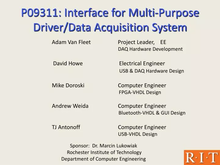
P09311: Interface for Multi-Purpose Driver/Data Acquisition System Adam Van Fleet Project Leader, EE DAQ Hardware Development David Howe Electrical Engineer USB & DAQ Hardware Design Mike Doroski Computer Engineer FPGA-VHDL Design Andrew Weida Computer Engineer Bluetooth-VHDL & GUI Design TJ Antonoff Computer Engineer USB-VHDL Design Sponsor: Dr. Marcin Lukowiak Rochester Institute of Technology Department of Computer Engineering
Project Overview • Main Goal: Investigate and implement a reliable FPGA interface, utilizing various communication channels, for the multi-purpose driver/data acquisition (DAQ) system designed in P08311. • Key high level customer needs / engineering specs: • Graphical User Interface (GUI) Utilizes Windows OS Displays Connection Status Displays Connection Speed • USB Communication Channel 1.5-12Mbps Transfer Rate 0% Data Transfer Loss • Bluetooth Comm. Channel 1.2-230kbps Transfer Rate 0% Data Transfer Loss • Meet all P08311 Design Req’s
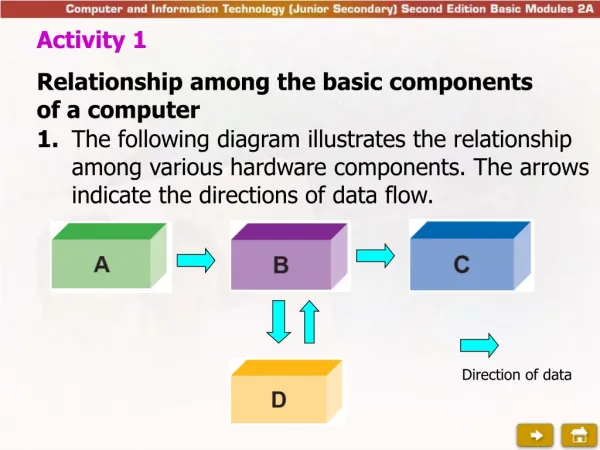
Hardware Design Concept P08311 DAQ Board Windows-Based PC ASIC or Robotics Input USB Adapter 12-pin (up to 8Mb/s xfer) 64-pin (3.84 Mbps xfer) USB RS-232 RS-232 (230 kbps xfer) Parani ESD210SK Bluetooth Dev. Kit Digilent Spartan-3 Board
System Flow Diagram DAQ FPGA PC `
Control Unit System Architecture FPGA USB 8 Mbps USB FIFO 3.84 Mbps Output Subsystem USB Data Routing Logic Input Conditioning USB Cable DAQ PC Serial UART Input Subsystem Output Conditioning 3.84 Mbps Tx Tx Bluetooth RS232 1.2 - 230 kbps Wireless Rx Rx Bluetooth Modules
Major Risk Assessment • Risk: Possibility for data transmission bottlenecks at FPGA interfaces • Action: Calculation of data rates (min and max) to ensure proper data flow • Risk: Interfacing FPGA to DAQ to ensure proper operation / data flow • Action: Preliminary testing of DAQ board, research into hardware connection
Current State of Design • Customer needs are met with design • System design and subsystems meet project specifications • Status: • Mock-Up of GUI designed has been programmed in C# • UART for bluetooth has been programmed in VHDL with communication to FPGA validated • Initial coding of USB logic and FPGA control logic /buffers under way, verification pending
Future Project Milestones MSD IWeek 11 • Design Finalized / Initial Testing Plan Devised MSD IIWeek 1-3 – Basic System Implementation / Testing • Completion of all VHDL programming for FPGA and subsystems • Establish GUI connection to FPGA • Full testing and analysis of system with base Bluetooth / USB configurations Week 4-7 – Project Exploration • Develop system with multiple Bluetooth / USB devices • System testing to determine optimum speed / configuration Weeks 8-9 • Analyze finished product for functionality of all systems • Prepare documentation / poster Weeks 10 • Finalize documentation / poster • Project wrap-up / Design Review