Download
1 / 50
540 likes | 778 Vues
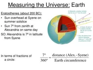
Global Positioning System: what it is and how we use it for measuring the earth’s movement. April 21, 2011. References. Lectures from K. Larson’s “Introduction to GNSS” http://www.colorado.edu/engineering/ASEN/asen5090/

E N D
Global Positioning System: what it is and how we use it for measuring the earth’s movement. April 21, 2011
References • Lectures from K. Larson’s “Introduction to GNSS” http://www.colorado.edu/engineering/ASEN/asen5090/ • Strang, G. and K. Borre “Linear Algebra, Geodesy, and GPS”, Wellesley-Cambridge Press, 1997 • Blewitt, G., “Basics of the GPS Technique: Observation Equations”, in “Geodetic Applications of GPS” • http://www.kowoma.de/en/gps/index.htm • http://www.kemt.fei.tuke.sk/predmety/KEMT559_SK/GPS/GPS_Tutorial_2.pdf • Lecture notes from G. Mattioli’ (comp.uark.edu/~mattioli/geol_4733/GPS_signals.ppt)
Basics of how it works • Trilateration • GPS positioning requires distance to 4 satellites • x,y,z,t • Earth centered, Earth Fixed • Why t? • What are some of reasons why measuring distance is difficult? • How do we know x, y, z, t of satellites?
GPS: Space segment • Several different types of GPS satellites (Block I, II, II A, IIR) • All have atomic clocks • Stability of at least 10-13 sec 1 sec every ~300,000 yrs • Dynamics of orbit? • Reference point?
Orbital Perturbations – (central force is 0.5 m/s2) From K. Larson
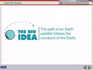
GPS: Space Segment • 24+ satellites in orbit • Can see 4 at any time, any point on earth • Satellites never directly over the poles • For most mid-latitude locations, satellites track mainly north-south
GPS Signal • Satellite transmits on two carrier frequencies: • L1 (wavelength=19 cm) • L2 (wavelength=24.4 cm) • Transmits 3 different codes/signals • P (precise) code • Chip length=29.3 m • C/A (course acquisition) code • Chip length=293 m • Navigation message • Broadcast ephemeris (satellite orbital parameters), SV clock corrections, iono info, SV health
GPS Signal • Signal phase modulated: vs Amplitude modulation (AM) Frequency modulation (FM)
C/A and P code: PRN Codes • PRN = Pseudo Random Noise • Codes have random noise characteristics but are precisely defined. • A sequence of zeros and ones, each zero or one referred to as a “chip”. • Called a chip because they carry no data. • Selected from a set of Gold Codes. • Gold codes use 2 generator polynomials. • Three types are used by GPS • C/A, P and Y
PRN Code properties • High Autocorrelation value only at a phase shift of zero. • Minimal Cross Correlation to other PRN codes, noise and interferers. • Allows all satellites to transmit at the same frequency. • PRN Codes carry the navigation message and are used for acquisition, tracking and ranging.
Schematic of C/A-code acquisition Since C/A-code is 1023 chips long and repeats every 1/1000 s, it is inherently ambiguous by 1 msec or ~300 km.
BASIC GPS MEASUREMENT: PSEUDORANGE • Receiver measures difference between time of transmission and time of reception based on correlation of received signal with a local replica The measured pseudorange is not the true range between the satellite and receiver. That is what we clarify with the observable equation.
COMPARE PSEUDORANGE and CARRIER PHASE • bias term N does not appear in pseudorange • ionospheric delay is equal magnitude but opposite sign • troposphere, geometric range, clock, and troposphere errors are the same in both • multipath errors are different (phase multipath error much smaller than pseudorange) • noise terms are different (factor of 100 smaller in phase data)
Atmospheric Effects • Ionosphere (50-1000 km) • Delay is proportional to number of electrons • Troposphere (~16 km at equator, where thickest) • Delay is proportional to temp, pressure, humidity.
Tropospheric effects • Lowest region of the atmosphere – index of refraction = ~1.0003 at sea level • Neutral gases and water vapor – causes a delay which is not a function of frequency for GPS signal • Dry component contributes 90-97% • Wet component contributes 3-10% • Total is about 2.5 m for zenith to 25 m for 5 deg
Tropospheric effects At lower elevation angles, the GPS signal travels through more troposphere.
Dry Troposphere Delay Saastamoinen model: • P0 is the surface pressure (millibars) • f is the latitude • h is the receiver height (m) Hopfield model: • hd is 43km • T0 is temperature (K) Mapping function: • E – satellite elevation ~2.5 m at sea level 1 (zenith) – 10 (5 deg)
Wet Troposphere Correction Less predictable than dry part, modeled by: Saastamoinen model: Hopfield model: • hw is 12km • e0 is partial pressure of water vapor in mbar Mapping function: 0 – 80 cm
Ionosphere effects • • Pseudorange is longer – “group delay” • • Carrier Phase is shorter – “phase advance” TEC = Total Electron Content
Determining Ionospheric Delay Where frequencies are expressed in GHz, pseudoranges are in meters, and TEC is in TECU’s (1016 electrons/m2)
Ionosphere-free Pseudorange Ionosphere-free pseudoranges are more noisy than individual pseudoranges.
Multipath • Reflected signals • Can be mitigated by antenna design • Multipath signal repeats with satellite orbits and so can be removed by “sidereal filtering”
Standard Positioning Error Budget UERE = User Equivalent Range Error
Intentional Errors in GPS • S/A: Selective availability • Errors in the satellite orbit or clock • Turned off May 2, 2000 With SA – 95% of points within 45 m radius. SA off, 95% of points within 6.3 m • Didn’t effect the precise measurements used for tectonics that much. Why not?
Intentional Errors in GPS • A/S: Anti-spoofing • Encryption of the P code (Y code) • Different techniques for dealing with A/S • Recover L1, L2 phase • Can recover pseudorange (range estimated using P-code) • Generally worsens signal to noise ratio
AS Technologies Summary Table Ashtech Z-12 & µZ Trimble 4000SSi From Ashjaee & Lorenz, 1992
GEOMETRIC RANGE • Distance between position of satellite at time of transmission and position of receiver at time of reception
PSEUDORANGE minus GEOMETRIC RANGE • Difference is typically dominated by receiver clock or satellite clock.
L1 PSEUDORANGE - L2 PSEUDORANGE • Differencing pseudoranges on two frequencies removes geometrical effects, clocks, troposphere, and some ionosphere
Geometry Effects: Dilution of Precision (DOP) Good Geometry Bad Geometry
Dilution of Precision Covariance is purely a function of satellite geometry
Positioning • Most basic: solve system of range equations for 4 unknowns, receiver x,y,z,t P1 = ( (x1 - x)2 + (y1 - y)2 + (z1 - z)2 )1/2 + ct - ct1 … P4 = ( (x4 - x)2 + (y4 - y)2 + (z4 - z)2 )1/2 + ct - ct4 • Linearize problem by using a reference, or a priori, position for the receiver • Even in advanced software, need a good a priori position to get solution.
Positioning vs. Differential GPS • By differencing observations at two stations to get relative distance, many common errors sources drop out. • The closer the stations, the better this works • Brings precision up to mm, instead of m.
Single Differencing • Removes satellite clock errors • Reduces troposphere and ionosphere delays to differential between two sites • Gives you relative distance between sites, not absolute position
Double Differencing • Receiver clock error is gone • Random errors are increased (e.g., multipath, measurement noise) • Double difference phase ambiguity is an integer
High precision GPS for Geodesy • Use precise orbit products (e.g., IGS or JPL) • Use specialized modeling software • GAMIT/GLOBK • GIPSY-OASIS • BERNESE • These software packages will • Estimate integer ambiguities • Reduces rms of East component significantly • Model physical processes that effect precise positioning, such as those discussed so far plus • Solid Earth Tides • Polar Motion, Length of Day • Ocean loading • Relativistic effects • Antenna phase center variations
High precision GPS for Geodesy • Produce daily station positions with 2-3 mm horizontal repeatability, 10 mm vertical. • Can improve these stats by removing common mode error.