Download
1 / 30
310 likes | 520 Vues
Pore and Sample Scale Unsaturated Hydraulic Conductivity for Homogeneous Porous Media Dani Or and Markus Tuller Dept. of Plants, Soils and Biometeorology, Utah State University.

E N D
Pore and Sample Scale Unsaturated Hydraulic Conductivity for Homogeneous Porous MediaDani Or and Markus TullerDept. of Plants, Soils and Biometeorology, Utah State University Tuller, M. and D. Or, 2001, Hydraulic conductivity of variably saturated porous media - Film and corner flow in angular pore space, Water Resour. Res. (next issue)
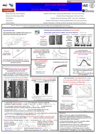
Millville Silt Loam Review of pore scale hydrostatics Unitary approach for capillarity and adsorption: Liquid films and the disjoining pressure concept. New model for basic pore geometry. Liquid configurations for different potentials are obtained by simplified AYL equation where interface curvature r() in pore corners isshifted by film thickness h(). Expressions for unit pore retention and liquid-vapor interfacial areas were statistically upscaled to represent Gamma distributed pore populations. Limitations: 2-D representation of a 3-D system; advantages: improved representation of physical processes (A & C), angular geometry, and quantifying L-V and S-W interfacial areas. films corners/ full pores
Clarification of a few open issues discussed in session of pore scale hydrostatics • Additional “snap-off” mechanism is associated with passage of invading non-wetting phase “finger” in the 3rd dimension (i.e. Main Terminal Meniscus) which would appear as a “hole” in the 2-D plane. • Note the rapid rupture of the liquid vapor interface and the formation of a new configuration after snap-off. • Equivalency between the van Genuchten (1980) model parameters and the new model parameters may be established as follows: • LmaxvG-1 (largest pore determines air entry value). • s (porosity and saturated water content). • (or SA) r (surface area x film determine residual water content). • n(both parameters determine the shape of statistical PSD).
More angular a r() r* The “trapped” microbe problem • The ratio r*/r() is 0.17, 0.33, 0.59 for corner angles (2) of 30o, 600 and 900, respectively. • More angular porous media delay l-v interfacial constraints for microbial aquatic habitats.
Outline – section 3 Hydrodynamics in homogeneous porous media • Estimation of capillary size distribution for hydrodynamic considerations • Statistical application of Poiseuille’s law and the standard BCC approach (cross-section only!) • Coupling flow in tubes with Darcy’s macroscopic flow equation [Childs and Collis-George, 1950; Fatt and Dykstra, 1951]. • Flow regimes in angular pores and slits (cross-section only!) • The assumption of interfacial stability for slow laminar flow. • Assembly of K() for a unit cell. • Upscaling to a population of unit cells (parallel flow pathways!) • Input parameters and upscaling procedure. • Examples – the role of film flow
Water Content - q - [m3 m-3] Matric Suction - [m] BCC-based prediction of unsaturated hydraulic conductivity K() • Extraction of radii distribution of capillary radii of the BCC (from retention data). • Application of hydrodynamic considerations, i.e., the volumetric discharge in a cylindrical tube is proportional to the 4th power of tube radius (Poiseuille’s law). (1) (2) L r P2 P1
BCC-based prediction of unsaturated hydraulic conductivity K() (cont.) • Statistical application of Poiseuille’s law for a bundle of capillaries coupled with Darcy’s macroscopic flow equation [Childs and Collis-George, 1950; Fatt and Dykstra, 1951; Burdine, 1953; Mualem, 1976; van Genuchten, 1980]. • K() function is constructed by summation of the discharge (for a unit-gradient) over all “tubes” that are liquid-filled at a given potential () divided by total sample cross-sectional area (voids and solids). nj Ks
BCC-based prediction of unsaturated hydraulic conductivity K() (cont.) • Geometrical and hydrodynamic aspects of real porous media were introduced into the BCC by consideration of a more complex capillary structures, for example cut-and-randomly rejoin concepts; or the effective flow through a pair of unequal capillaries such as treated by Mualem, [1976]. • The concept of tortousity (Lc/L) improves BCC model predictions. (Mualem, 1976) Lc L
Hydrodynamic Considerations for Angular Pores • Equilibrium liquid-vapor interfacial configurations at various potentials serve as fixed boundaries for the definition of flow regimes (laminar) in angular pore space (film and corner flows). • The simple cell geometry and well-defined boundary conditions permit solution of the Navier-Stokes equations for average liquid velocity for each flow regime (i.e., geometrical feature). • Analogy with Darcy’s law is invoked to identify the coefficient of proportionality between flux and hydraulic gradient as the hydraulic conductivity for each flow regime under consideration.
Full duct Parallel Plates Corner Film Primary Flow Regimes in a Unit Cell (1) Flow in ducts and between parallel plates for completely liquid-filled pores and slits. (2) Flow in thin liquid films lining flat surfaces following pore and slit snap-off. (3) Flow in corners (bounded by l-v interface) of the central pore.
Hydraulic conductivity of full ducts • Triangular Duct • Square Duct with Bs (L1=L2) given as: • Rhombic Duct ( tube)
Hydraulic conductivity in high-order polygons/rhombic pores Rhombic Duct (tube) The area constant An is given as: As n Pore radius r and edge size L for large n are related by: Substitution into the rhombic duct equation “recovers” Poiseuille’s law for mean velocity (unit gradient) in a cylindrical tube:
r() Flow in corners bounded by a liquid-vapor interface • Expressions for flow in partially-filled corners as a function of chemical potential , and corner angle , were based on Ransohoff and Radke (1988) solution to the Navier-Stokes equation: • The key lies in the explicit dependence on radius of interfacial curvature r(). • Tabulated values of the dimensionless flow resistance as a function of corner angle were parameterized.
Laminar flow in thin liquid films • Expressions for thin film flow considering modified viscosity near the solid surface (for thin films h<10 nm) were developed: with: for exponential viscosity profile. • For thicker films (h>10 nm) the standard relationships for mean flow velocity vs. film thickness and constant viscosity are used:
Modified water viscosity near clay surfaces • Exponential viscosity profile near the solid clay surface was measured by Low (1979). • Flow is thin films (h<10 nm) is strongly modified. • Implications for hydraulic conductivity and flow rates through clay layers. k1,k2 permeabilities [m2] h1,h2 slit spacing [m] 1,2 viscosities [Pa s]
Corner Flow Primary Flow Regimes in a Unit Cell Film Flow h(m )> 10nm Film Flow h(m ) 10nm e Dimensionless flow resistance h Viscosity of bulk liquid A(m) Function for modified viscosity P Hydraulic pressure
- 0.26 J/kg - 0.16 J/kg - 0.15 J/kg - 0.17 J/kg - 0.25 J/kg 1 [mm] 0 - 0.14 J/kg - 0.18 J/kg - 0.25 J/kg - 0.50 J/kg - 1.20 J/kg 4 mm 0 s 4 s 10 s 12 s Interfacial stability - A critical assumption • A critical assumption regarding stability of equilibrium liquid-vapor interfacial configurations under slow laminar flow... • Indirect “evidence” • Time sequence photographs of water drop formation and detachment from a vertical v-shaped groove. Note l-v interface above the drop remains constant during flow! (Or and Ghezzehei, 1999). • The capillary number (Ca) is a measure of the relative importance of viscous to capillary forces – typical values are in the range of Ca=10-5 for soils (Friedman, 2000)
Full duct Parallel Plates Corner Film Primary Flow Regimes in a Unit Cell (1) Flow in ducts and between parallel plates for completely liquid-filled pores and slits. (2) Flow in thin liquid films lining flat surfaces following pore and slit snap-off. (3) Flow in corners (bounded by l-v interface) of the central pore.
Primary Flow Regimes in a Unit Cell Parallel Plates (slits) Triangular Duct Square Duct Circular Duct (tube) Corner (bounded by l-v) Thick Film Flow (h(m )> 10nm) Thin Film Flow (h(m )< 10nm)
Full duct Full slits Hydraulic Conductivity for a Unit Cell • Saturated and unsaturated hydraulic conductivity for the unit cell was derived by weighting the conductivities of each flow regime over the liquid-occupied cross-sectional areas and dividing by total cross-sectional area (AT) including the solid shell. Saturated Hydraulic Conductivity KS Slit hydraulic conductivity KD Duct hydraulic conductivity (e.g., triangular is given by: AT Cross sectional area:
Unsaturated Hydraulic Conductivity for a Unit Cell • Unsaturated hydraulic conductivity for the unit cell was derived by weighting the conductivities of each flow regime over the liquid-occupied cross-sectional areas and dividing by total cross-sectional area. Corner After Pore Snap-Off After Slit Snap-Off Film KS Slit hydraulic conductivity KD Duct hydraulic conductivity KF(m) Film hydraulic conductivity KC(m) Corner hydraulic conductivity
Hydraulic Functions for a Single Unit CellFitted to Measured Data[Hygiene Sandstone] Relative Hydraulic Conductivity Liquid Saturation L=0.033 mm, =0.0012, =0.0001 Ks=3.7 m/day (measured Ks=1.1 m/day)
L4 L5 L1 L2 L3 L6 Upscaling from pore- to sample-scale • A statistical approach using Gamma distributed cell sizes (L) is employed for upscaling unit cell expressions for liquid retention and hydraulic conductivity to represent a sample of porous medium. • Upscaled equations for liquid retention were fitted to measured SWC data subject to porosity and SA area constraints. • The resulting best fit parameters are used to predict sample scale saturated and unsaturated hydraulic conductivities. Gamma Distribution for L Slits f(L) Dry Wet L1 L2 L3 L4 L5 L6 m1 m2 m3
Model input parameters for upscaling • Choice of unit cell shape • Use of liquid retention data, constrained by: • Soil porosity, and • Specific surface areaPossibility of using other types of distributions • Equivalency between the van Genuchten (1980) model parameters and the new model parameters: • LmaxvG-1 (largest pore determines air entry value). • s (porosity and saturated water content). • r (surface area x film determine residual water content). • n(both parameters determine the shape of statistical PSD).
Upscaling Results for a Clay Loam Soil[Source: Pachepsky et al., 1984] Relative Hydraulic Conductivity Liquid Saturation
Upscaling Results for a Sandy Loam Soil[Source: Pachepsky et al., 1984] Relative Hydraulic Conductivity Liquid Saturation
Upscaling Touchet Silt Loam with Variable [Source: van Genuchten, 1980] Fitted Saturation Predicted K(h)
Resulting Hydraulic Functions Parameter Estimation Input Information Hydrodynamic Considerations Sample Scale Parameter Estimation Scheme
An alternative framework for hydraulic conductivity modeling in partially saturated porous media, considering film and corner flow phenomena was developed. Equilibrium liquid-vapor interfacial configurations for various chemical potentials were used as boundary conditions to solve the Navier-Stokes equations for average velocities in films, corners, ducts, and parallel plates. Analogy to Darcy’s law was invoked to derive proportionality coefficients between flux and hydraulic gradient representing average hydraulic conductivity for the various flow regimes. Pore scale expressions were statistically upscaled to represent conductivity of a sample of partially-saturated porous medium. Summary