Execution Architecture View
Execution Architecture View. ZHAO Jianhua Dept. of Computer Sci&Tech Nanjing University. Introduction(1). The execution view describes the structure of a system in terms of its runtime platform elements. How the functionality is assigned to the elements

Execution Architecture View
E N D
Presentation Transcript
Execution Architecture View ZHAO Jianhua Dept. of Computer Sci&Tech Nanjing University
Introduction(1) • The execution view describes the structure of a system in terms of its runtime platform elements. • How the functionality is assigned to the elements • How the resulting runtime instances communicate. • How physical resources are allocated to them. • Also the location, migration, and replication of the runtime instances.
Introduction(2) • The execution view will likely change overtime, so the architecture should be easily adaptable. • The resource decisions you make for a component will likely affect the resources available for other components. • So it is easier to consider this aspect of the system separately.
Introduction(3) • The execution view is used for performance, monitoring, and tuning as well as for debugging and service maintenance.
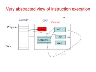
Introduction(4) • When the system has more than one process, the execution view diverges from the module view. • Client/Server: the “client API library” is a part of the server in module view, but it is part of client process in execution view.
Introduction(5) • The execution view also captures replication. • for example, one server, multi-clients • Expose the concurrency requirement for the server. • The execution view helps to pinpoint where protocols for things like interprocess communication and concurrency are needed.
Introduction(6) • Another reason: Better prepare for change: • You would most likely to adapt to changes in the software/hardware due to advances in technology. • Tuning the performance for system with tight performance requirement. (i.e. For the systems with tight performance requirement.)
Design Activities for the Execution Architecture View(1) • Global analysis • Runtime entities • Communication paths • configuration • resource allocation
Design Actives for the Execution Architecture View(2) Hardware Architecture Conceptual View Global Analysis • Figure 6.1, PAGE 127 Central Design Tasks Central Design Task runtime entities comm. path Module View Central Design Tasks global evaluation exe. configuration Codel View Central Design Tasks Final Design Task: resource allocation
Global Analysis(1) • Identify the factors that affect the execution view: performance requirements, communication mechanisms. • Analysis the hardware platform. • a list of hardware components, • the topology or interconnection of these components. • Analyze the changeability of the hardware.
Global Analysis(2) • Analysis the software platform. • Know the infrastructure software between your product and the hardware platform, including OS, networking software, middleware layers, DBMS. • Analyze the changeability of software platform.
Meta-model for platform elements HardwareRes SoftwarePlatform • FIGURE 6.2, PAGE 128 assigned to PlatformElement PlatformResource contain > consume > Thread Task Queue Shared Memory DLL CPU Time Timer Mem Process Socket File SharedLib AddressSpace Semaphore
Central Design Tasks:Runtime Entities(1) • Decide how to map conceptual components and modules to the platform elements. • The modules will be assigned to runtime entities. • A runtime is allocated to one of the platform elements defined for the software platform.
Central Design Tasks:Runtime Entities(2) • We may start by assigning conceptual components to platform elements. Then refine the partitioning by mapping modules to runtime entities. • There may be runtime entities that have no direct correspondence to modules: daemons, server processes.
Central Design Tasks:Runtime Entities(3) • The next step: consider the resource sharing that is allowed or required among the runtime entities • files, buffers, servers… • Define the runtime characteristics of each runtime entity: • host type, replication, concurrency control mechanisms used, …
Meta-modelfor runtime entities • Figure 6.3. Page 129 Platform Element 1 ^is a * < assigned to Runtime Entity Modules * *
Central Design Tasks:Communication Paths • Identify the expected and/or allowable communication paths between runtime entities. • mechanisms: IPC, RPC, … • resources: • The implementation of the protocols is often distributed among the runtime entities participating in the communication.
Meta-modelfor communication paths Communication Mechanism Platform Element • Figure 6.4, PAGE 130 consume > DCOM IPC RPC ^ is a ^ use mechanism Communication Path Runtime Entity < communicate over
Execution Configuration(1) • Describe the system’s runtime topology • characterizing the instances of the runtime entities • how they are interconnected. • The distinction between a runtime entity and its runtime instances. • A runtime entity is often replicated. Each of the incarnations is a separate runtime instance.
Execution Configuration(2) • Determine each runtime instance and its attributes. • the corresponding runtime entity, • host name, • resource allocation, • information about creation and termination.
Execution Configuration(3) • Describe the interconnection of the runtime instances. • which runtime instances communicate, • temporary communication paths. • permanent communication paths. • More common for the execution configuration to contain runtime instances.
Execution Configuration(4) • Execution configuration is generally dynamic: • most systems have different phases: start-up, shutdown, operating, … The configurations in different phases are different. • Describe how the configuration changes over time, and how those changes are controlled. • Need to determine and describe how the configuration changes overtime, and how those changes are controlled.
Global Evaluation • Evaluate the design according to the following. • Global Analysis: Strategies for performance, dependability. • Conceptual View: Concurrency among conceptual components. • Modules View: The runtime entities and how they communicate, constrained by modules. • Hardware architecture: Resource and platform.. • Consider the implementation cost, avoid complex algorithms.
Final Design Task: Resource Allocation • Take the runtime instances and budgets, • allocate the runtime instances to particular hardware devices. • Assign specific values to the budgeted attributes.(process priorities)
Final Design Task: Resource Allocation • Resources to be allocated were identified during the global analysis task. • You can determine the resource according to the hardware and software platforms. • The resources including shared memory, CPU time, band-width, … • If there are not enough resource, redesign may be needed.
Final Design Task: Resource Allocation(2) • The allocation decisions made are fairly localized. • For larger systems, it is useful to deal with more than one resource or process at a time: resource may be allocated to a collection of processes responsible for related functions.
Design of Execution Architecture View: IS2000(1) • Relevant Issue and Strategies • Issue: Skill Deficiencies • Avoid use of multiple threads • Encapsulate multi-process support facilities
Design of Execution Architecture View: IS2000(2) • New issue: High Throughput is identified because of the very high data rate of the probe hardware.
Issue card for High Throughput • The probe hardware has a very high data rate. • The processing rate must keep up with the data rate. • The development team is deficient in the skills about multiple threads and multiple processes.
Issue card for High Throughput(2) • Influencing Factors: • O2.3, O2.4, P7.1, T1.2, T3.2 • Solution: • Maximize the use of the processor by maximizing concurrency. • An additional CPU is needed. The new one can run a real-time OS, or a common UNIX. • We must determine: technically feasiblity, impact on the cost, and the design.
Issue card for High Throughput(3) Strategies: • Map independent threads of control to processes. • take the advantage of the low cost of process creation/destruction. Complements the strategy: Avoid use of multiple threads. • Use an additional CPU. • consider a dedicated real-time CPU.
Global Analysis • Requirement • a single CPU, additional CPU if necessary • limit memory size: 64M • New strategies • Use an additional CPU • Map independent threads of control to processes.
Issue Real-Time Acquisition Performance • Only one strategy so far. • The acquisition performance is measured by the size and number of images. • Estimating the performance earlier can provide valuable feedback. • New strategy to estimate the performance • Use rate monotonic analysis to predict performance • http://www.sei.cmu.edu/str/descriptions/rma_body.html
Issue Real-Time Acquisition Performance • We may need to adjust process boundaries as the system is implemented. • A module previousely assigned to a process may be assigned to another later.
Issue card for Real-Time Acquisition Performance • Meeting real-time performance requirements is critical to the success of the product. • The source code that implements functional processing must meet the performance constraints. • Influencing Factor: • T1, T3, P3.1, P3.2
Issue card for Real-Time Acquisition Performance • Solution • Partition the system into separate components for algorithms, comm., … • Use techniques to predict performance to help in the early identification of performance bottlenecks. • Strategies: • Separate time-critical components form nontime-critical components.
Issue card for Real-Time Acquisition Performance • Strategies(continued) • Develop guidelines for module behavior. • i.e. Modules have a single thread of execution, reentrant, … • Use flexibile allocation of modules to process • So that the system can be tuned to achieve the required performance. • Use rate monotonic analysis to predict performance.
Issue Resource Limitations • Use QNX, a UNIX-like OS to provide support for meeting the real-time processing requirements. • Use only the features that are POSIX compliant except QNX proxies.
Issue Resource Limitations • For the memory limitation: • For the selected OS(QNX), processes consume software resources. But it’s inexpensive to create or destroy process. • Only those necessary process are needed. • Strategy for resource limitation • Limit the number of active processes.
Issue card forResource Limitations • The arcitecture must cope with the limitations of the resource limitations. • Should provide guidance for making design choices, and the system should be easy to adapt. • We should limit the number of active processes that can run at the same time. We need to terminate and restart processes in this case.
Central Design Tasks • Runtime Entities, Communication paths, configuration. • These activities can not be done in a strict sequential order. • They are tightly coupled.
Begin Defining Runtime Entities • Starting point: associate each high-level conceptual component with a set of execution elements. • For IS2000, put each thread in its own process to avoid multithreaded process. • Use UML deployment diagram to show on which hardware resource these processes will run.
Overview of execution architecture view :Real-Time CPU • Figure 6.5, PAGE 137 :Probe Control :Acquisition Management :Acquire :Data Collection :Image Proc. :Post Proc. :Monitor :Image Collection :Export :Comm
Assign the modules • Start with the higher risk parts of the system first: ImageProcessing(computationally expensive). • We use just one pipeline to illustrate the design tasks.
The modules MClient SImaging • Figure 5.8 MFramer MImager MDataManager MPipeline MPacket MImageMgr MAcqControl MPacketMgr MPaccketizer MPipelineMgr
Assign the modules(2) • All the following modules should be mapped to a runtime element: • Mpacketizer, MPacketMgr, Mframer, MAcqControl, MPipelineMgr, … • Start with the assignments that are most straightforward, then adjust the assignments
Assign the modules(2) • If there is a simple one-to-one correspondence between conceptual components and modules, we assign a module to a process or a thread. • A separate processes for each of the pipeline stages because of Map independent threads of control to processes. • Mclient • MDataCollect
Initial Processes for the imaging subsystem <<process>> EDataCollection <<process>> EFrammer • Figure 6.7, Page 139 <<process>> EDataCollection <<module>> MDataCollect <<module>> MFramer <<module>> MClient <<module>> MAcqControl <<process>> EImager <<module>> MImager
Determine the communication paths and mechanisms • Examine the dependencies among these modules. • The communication between image pipeline client and the imaging subsystem. • Takes place through MAcqControl. • Mclient access the MAcqControl. • Link all the MAcqControls into the process with Mclient so that we can use local procedure call to communicate.
Pipeline Manger • Consider the communication between individual pipeline stages(performance). • New strategies for the performance of communication between pipeline stages • use shared memory to communicate between pipeline stages. • to eliminate any unnecessary data copying in the acquisition and processing pipelines.