OVER VIEW, ARCHITECTURE MAIN COMPONENTS
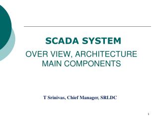
OVER VIEW, ARCHITECTURE MAIN COMPONENTS. SCADA SYSTEM. T Srinivas, Chief Manager, SRLDC. SCADA SYSTEM. OVER VIEW ARCHITECTURE MAIN COMPONENTS. SCADA : Supervisory Control and Data Acquisition.

OVER VIEW, ARCHITECTURE MAIN COMPONENTS
E N D
Presentation Transcript
OVER VIEW, ARCHITECTUREMAIN COMPONENTS SCADA SYSTEM T Srinivas, Chief Manager, SRLDC
SCADA SYSTEM • OVER VIEW • ARCHITECTURE • MAIN COMPONENTS
SCADA :Supervisory Control and Data Acquisition • It is the system responsible for gathering, processing, and displaying information about the state of a monitored system. • From a SCADA control center, operators and application programs can oversee and change the operating state of monitored devices.
Southern Regional Load Despatching Facilities Bangalore RLDC 2 Sec Chennai SCC UTP Bangalore Hyderabad SLDC Kalamassery 2 Sec TVM LGR WGL TVM MDI GTR CDP VIJ ERD Sub LDC INT SCADA 10 Sec RTU RTU RTU RTU RTU RTU RTU RTU RTU RTU RTU
Scada System - Overview TYPICAL SCADA SYSTEM C TX O Rx M E M Q N P T R T U T P R A A N N E S L D U C E R C TX O RX M E M Q N P T SCADA H/W & S/W C & R PANEL MEDIA FIELD UNIT / RTU COMMN MEDIA CONTROL CENTRE SUBSTATION / GEN STATION
Scada System - Architecture • First Generation – Monolithic • Second Generation – Distributed • Third Generation – Networked
Scada System - Architecture MONOLITHIC SCADA SYSTEM
Scada System - Architecture MONOLITHIC SCADA SYSTEM Computing Centered with Main Frame Non existant of Networks Centralised System Standalone sytem
Scada System - Architecture DISTRIBUTED SCADA SYSTEM
Scada System - Architecture DISTRIBUTED SCADA SYSTEM • Advantage of developments and • improvement in system miniaturization and Local Area Networking (LAN) technology to distribute the processing across multiple systems. • Multiple stations, each with a specific • function, were connected to a LAN and shared information with each other in real-time
Scada System - Architecture DISTRIBUTED SCADA SYSTEM • Communications processors, primarily • communicating with field devices such as RTUs. • operator interfaces, providing the human-machine interface (HMI) for system operators. • calculation processors or database servers.
Scada System - Architecture DISTRIBUTED SCADA SYSTEM • Network-connected systems served not only to increase processing power, but also to improve the redundancy and reliability of the system as a whole. • Distributed architecture often kept all • stations on the LAN in an online state all of the time.
Scada System - Architecture NETWORKED SCADA SYSTEM
Scada System - Architecture NETWORKED SCADA SYSTEM • The major improvement in the third • generation is that of opening the system architecture, utilizing open standards and protocols and making it possible to distribute SCADA functionality across a WAN and not just a LAN. • There are still multiple networked systems, sharing master station functions. There are still RTUs utilizing protocols that are vendor-proprietary.
Scada System - Architecture NETWORKED SCADA SYSTEM • Utilization of off-the-shelf systems makes it easier for the user to connect third party peripheral devices (such as monitors, printers, disk drives, tape drives, etc.) to the system and/or the network. • Because of “open” or “off-the-shelf” systems, SCADA vendors have gradually gotten out of the hardware development business.
Scada System - Architecture NETWORKED SCADA SYSTEM • Advantage of the use of WAN protocols such as the Internet Protocol (IP) for communication between the master station and communications equipment. • Advantage brought about by the distribution of SCADA functionality over a • WAN is that of disaster survivability.
S C A D A / E M S VL A N (DMZ) DATA ACQUISITION VLAN Control center Architecture Dual Monitor Training Consoles DTS Server SO WorkStation (Dual Monitor) SO WorkStation (Dual Monitor) SO WorkStation (Dual Monitor) SO WorkStation (Dual Monitor) PC PC PC PC PC PC UPS, CMC, RD, PDS, ISR, NMS / Management LAN RTUs on 60870-5-101 Protocol Serial Cards (including 8 pair of modems) /Splitters RTU on 104/ PMU 0n C37.118/ other IP devices NETWORK Router cum Firewall 2 Nos. RTUs on Other Protocol CFE Servers 2 No. GPS , Time and Frequency Displays Renewable Control / mon Database Servers EMS Servers Historian SCADA NAS Storage SCADA Servers WorkStation LAN LCD / Video Projection IT application servers (DMZ) Routers at RLDCs and SLDC Router cum Firewall 2 Nos. ICCP Servers PDS, ISR, NMS LAN RD, CMC, UPS & SERVER MANAGEMENT LAN Programmer Development Server (1 Nos.) Report Generation Developmental Workstation Printers (B/W & Color) ISR Servers 2 No. NMS Servers CORPORATE LAN Remote WorkStation for Boss (Single monitor No controls) UPS Monitoring System CMC Server Management Console Identity Server Replica Servers Secure VPN ABT Scheduling, Poc & Market Operation Energy accounting Web Servers FTP Server Corporate NAS Storage Redundant Internet from different service provider Fig 1
Scada System – Main Components • Field Data Interface Devices • Communication Network • Central Host Computer • Operator Workstations and Software Components
Scada System – Main Components Field Data Interface Devices • "eyes, ears and hands" of a SCADA system • Before any automation or remote monitoring can be achieved, the information that is passed to and from the field data interface devices must be converted to a form that • is compatible with the language of • the SCADA system.
Scada System – Main Components Field Data Interface Devices • To achieve this, some form of electronic field data interface is required – RTU • RTU - primarily used to convert electronic signals received from field interface devices into the language (known as the Communication protocol) used to transmit the data over a communication channel.
Scada System – Main Components Field Data Interface Devices • Sensors/transducers that convert physical parameters to electrical signals. • Signal conditioning circuitry to convert sensor signals into a form that can be converted to digital values. • Analog-to-digital converters • A Scada system to process this digital data.
HARDWARE CONNECTIVITY DIAGRAM FOR SCADA AT SUBSTATION / GEN.STATION RS232 PORT TRANSDUCER PANEL REMOTE TERMINAL UNIT F R O M S W I T C H Y A R D - F I E L D P T SEC 110VAC TRANSDUCER I/P TERMINAL COMMN BOARD MAIN CPU BOARD PSU MW MVAR VOLT CT SEC 1 AMPS TRANSDUCER O/P TERMINAL A N A L O G I / P D I G T A L I / P C O N T R O L O/P EVENT LOGGER PANEL D R I V E R R E L A Y TERMINAL BLOCK TERMINAL BLOCK TERMINAL BLOCK
Basic Data Acquisition CT CB Pannel control PT Close Trip Potential Free Contact Field TRANSDUCER DAS NO Coil for Close NC Coil for Trip RTU Dig In RTU Ang In RTU Dig out
TRANSDUCERS • CLASSIFICATION • SELF POWERED/AUXILARY POWERED • INPUT • VOLTAGE/CURRENT • OUTPUT • 0-10mA, 4-20mA, 0-5mA 0-5v,0-10v • OUTPUT IMPEDANCE • 500Ω,1000Ω,2000Ω • ACCURACY • 0.2 CLASS, 0.5 CLASS, CLASS 2 AND ABOVE
A/D CONVERSION AT RTU LEVEL(16 BIT ADC). FOR MW / MVAR TRANSDUCER: INPUT: PT SEC PHASE TO PHASE : 110VAC CT SEC TWO PHASE CURRENT (R & B): 1 A. OUTPUT : 4 – 20mA(TRANSDUCER OUTPUT) IN ADC: AT 4mA = 6553 Count AT 20mA = 32767 Count 12mA IS THE CENTRE POINT. (+/- 0.1% IS THE ACCEPTABLE RANGE OF ERROR ON FULL SCALE)
TELEMETRY FOR SCADA P Q DS P Q SS P Q SS DS DC SS DS SS V F SS SS SS SS SS SS SS SS V F SS SS DS P Q DS DS SS • THE PARAMETERS ARE MONITORED FOR FOLLOWING STATIONS : • Substations 220 KV and above • 132/110KV AC Interstate Tie lines and in loop of 220 KV transmissions system • Generating Station above 50MW capacity. • Significant stations identified by constituents Q O SS P Q O MW MVAR TAP POSITION F V FREQUENCY VOLTAGE SINGLE STATUS ISOLATOR POSIITION, PROTECTION, LOSS OF VOLTAGE SS DOUBLE STATUS CIRCUIT BREAKER POSITION DS DIGITALCONTROL CIRCUIT BREAKER CONTROL DC
Scada System – Main Components Communications Network • Intended to provide data transfer between the central host computer servers and the field-based RTUs • The Communication Network refers to the equipment needed to transfer data to and from different sites. The medium used can either be cable, telephone or radio.
Scada System – Main Components Communications Network • Historically,SCADA networks have been dedicated networks • With the increased deployment of office LANs and WANs as a solution for interoffice computer networking, there exists the possibility to integrate SCADA LANs into everyday office computer networks.
Scada System – Main Components Communications Network The foremost advantage of this arrangement is that there is no need to invest in a separate computer network for SCADA operator terminals. In addition, there is an easy path to integrating SCADA data with existing office applications, such as spreadsheets, work management systems, data history databases.
Communication System Lingasugur
Scada System – Main Components Central Host Computer Network of computer servers that provide a man-machine operator interface to the SCADA system. The computers process the information received from and sent to the RTU sites and present it to human operators in a form that the operators can work with.
Scada System – Main Components Central Host Computer Operator terminals are connected to the central host computer by a LAN/WAN so that the viewing screens and associated data can be displayed for the operators. SCADA systems are able to offer high resolution computer graphics to display a graphical user interface or mimic screen of the site.
Scada System – Main Components Operator Workstations and Software Components Operator workstations are most often computer terminals that are networked with the SCADA central host computer. The central host computer acts as a server for the SCADA application, and the operator terminals are clients that request and send information to the central host computer based on the request and action of the operators.
Scada System – Main Components Operator Workstations and Software Components An important aspect of every SCADA system is the computer software used within the system. The most obvious software component is the operator interface or Man Machine Interface/Human Machine Interface (MMI/HMI) package Many SCADA systems employ commercial proprietary software upon which the SCADA system is developed
Scada System – Main Components Operator Workstations and Software Components Central host computer operating system Operator terminal operating system Central host computer application Operator terminal application
Scada System – Main Components Operator Workstations and Software Components Communications protocol drivers Communications network management software RTU automation software
Scada System – Main Components Operator Workstations and Software Components HMI -DAC -UI -DMC -ALARM EVENTS -ICCP -TDS
DAC MODULE (FOR SR ULDC) Scans the RTUs cyclically or on demand by the user The periodicity of scan can be defined Analog Data – 10 SECONDS Status Data – By Exception / Integrity check every 10 min SOE Data processing
Data types SCADA processes and stores three different types of data: • Analog Measurement, • Status (CircuirtBreakers and Isolators Positions), and • Count data (Like energy, Rainfall during the day etc).
Data Type • Analog Data : • Analogs are numeric values representing the state of variable-state devices, such as power lines, transformers etc • In the monitored system a physical variable is usually measured by a transducer, and the output of the transducer is passed through an analog-to-digital (A/D) converter in the RTU . • Status Data : • Status values represent the state of devices, such as circuit breakers, tap changers
Data polling method • Analogs are defined as periodic/Cyclic data . • The periodicity varies from 10 seconds to 15 seconds depending upon the quantity of data and available bandwidth . • Digital input state changes are to be reported spontaneously . • The Digital input data have higher priority than Analog values.
Data Flow 45 NLDC
Digital Data Potential free contacts are used to transfer switch position to control centre.
Sequence Of Events • Sequence of events provides milli secs accurate time of status changes for devices monitored by Remote Terminal Units . • The RTU clock is synchronized periodically by the control center clock . • Reading its internal clock when a SOE status point changes state . • Time stamped digital data stored in RTU buffer and transferred as file or Digital data with time stamped is transferred for SOE
UI & DMC • The UI subsystem facilitates interface to the User • It is through this module, the display, the real time status of the power system are viewed by the user. • The status of the hardware & logical devices, the communication with the RTU etc .. are closely monitored and failures are reported.
WS2 WS3 WS4 WS5 WS1 Switch AP-3 BACKUP SERVER RSCC, BANGALORE CONTROL CENTRE WORK STATIONS DUAL LAN FRONT END PROCESSORS WS7 WS6 DTS SYSTEM FE-1 FE-2 AP-7 AP-8 DTS SERVER DTS SERVER APPLICATION PROCESSOR RAID PNA:POWER NETWORK ANALYSIS COPS: COMPREHENSIVE OPERATION PLANNING AND SCHEDULING ICCP: INTER CONTROL CENTRE COMMUNICATION PROTOCOL RAID:- REDUNDANT ARRAY OF INDEPENDENT DISKS AP-1 AP-2 AP-4 AP-5 AP-6 DATA SERVER PNA/ICCP SERVER COPS SERVER SCADA AGC BACKUP SERVER 34