Module Architecture View
This module emphasizes the differences between the conceptual and module views in software architecture, aiming to bridge the gap between functionality and implementation. It discusses how image-processing pipelines operate, illustrating interactions through pointers and connectors. The module view represents a refined structure of the conceptual view, detailing how elements are decomposed and organized into modules and layers. It also highlights the importance of global analysis in guiding design decisions, focusing on factors such as modifiability, performance, and maintainability.

Module Architecture View
E N D
Presentation Transcript
Module Architecture View ZHAO Jianhua Dept. of Computer Sci&Tech Nanjing University
Introduction • The module view and the conceptual view make explicit different things. • Main purpose: bring you closer to the system’s implementation in software. • making explicit how the functionality is mapped to the implementation. • making explicit the relationships among the implementing elements.
Introduction(2) • For image-processing pipeline of IS2000 • In the conceptual view: the images are passed from one pipeline stage to the next. • In the module view: each stage requests a pointer to its image data from the pipeline manager, then reads and writes the image using the pointer. (how the image data are transferred).
Introduction(3) • Another example: two components communicate over a connector with call/return semantics. • if two components are in the same CPU, the communication is implemented as a local call. • if two components are in different CPU, the communication is implemented as RPC. we must consider supporting services • This information is not explicit in conceptual view.
Introduction(4) • The module view is not simply a refinement of the conceptual view. • Mapping conceptual elements to modules is a repartitioning. • The components, connectors, roles, ports can be grouped and splitted. • The modules must also take into account the implementation constraints.
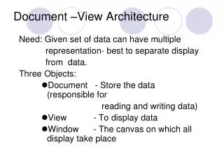
Introduction(5) • The conceptual and module views are based on two fundamentally different models. • Conceptual view: components(functionality) , interact using connectors(control). • Module view: all the application functionality, control functionality, adaptation, and mediation are mapped to modules. Modules interact through the interfaces.
Introduction(6) • The module view define the modules, and their inherent relationships. • How they are combined into a particular product is defined in execution view, not module view.
Introduction(7) • Modules are organized into two orthogonal structures: decomposition and layers • decomposition captures the way the system is logically decomposed into subsystems and modules. • layers constrains its dependencies among the modules.
Design Activities for the Module Architecture View • Global analysis • Central design tasks • modules • layers • global evaluation • Interface design
Diagram of design tasks Execution View conceptual view Central Design Tasks • Figure 5.1, PAGE 99 Module View central design tasks Central Design Tasks Final Design Task modules layers Global Analysis interface design global evaluation Code View Central Design Tasks
Global Analysis • Should check all the factors, especially: • For organizational factors: staff skills, process and development environment, development budget. • For technological factors: the general-purpose hardware, software technology, and standards categories.
Global Analysis • The following strategies are important • Guide the decision: strategies related to modifiability, portability, and reuse. • Your decision should support: strategies related to performance, dependability and failure detection, reporting, recovery.
Central Design Tasks • Map conceptual elements to subsystems and modules, create layers, and assign modules to layers. • Determine the interfaces of the modules and layers. • Guiding the decisions are: • strategies from global analysis • experience • and general software engineering knowledge.
Central Design Tasks: Modules • Map the conceptual elements to modules or subsystems. • A subsystem usually corresponds to a higher level conceptual component. • A module can also be decomposed into other modules • only the leaf modules correspond to implemented code.
Central Design Tasks: Modules(2) • Modules interact with each other through the interfaces. • The service provided by a module are defined by the interfaces it provides. • A module uses another when it requires the interface provided by the other.
Central Design Tasks: Modules(3) • The conceptual elements get mapped to the modules. • assign the modules a responsibility • determine their decomposition and use relationships. • The initial mapping maybe a direct one-to-one map from the conceptual elements to modules. • You may refine and split modules or combine them after initial mapping.
Central Design Tasks: Modules(4) • Some modules that don’t have counterparts in conceptual view may be added. • failure detection or recovery. • services needed by existing modules. • Modules should be decomposed to the point when • the responsibilities of each module are well understood. • The risk of implementation or integration is low.
Meta-model for subsystems and modules • Figure 5.2, PAGE 101 Subsystem provide > 0..1 Interface contain> * * * * * require > * Module {Module A uses module B when A requires an interface that B provides.} * * 0..1
Central Design Tasks: Layers • Layers organize the modules into partially ordered hierarchy. • A module can use other modules in same layer. • A module can use modules in other layer, the interface required and provided by the modules must also be required and provided by the layers.
Central Design Tasks: Layers(2) • Layers are a way of reducing complexity, supporting reuse, and providing independence. • Ways to identify the layers: • start identifying the layers as the modules are identified. • Begin with a set of layers based on your experience from similar applications in the domain. • A combination of the two.
Meta-model for layers < provide • Figure 5.3, PAGE 102 Interface * <contain < require Module Layer 0..1 * * 0..1 * use
Global Evaluation • You can get guidance from multiple sources: • conceptual view design • strategies from global analysis • your experience with software architecture • general knowledge of architecture and SE • Deciding which source of information to use at which time.
Global Evaluation • Lookout for the feedback to the tasks and decisions you made earlier in the design. • Evaluate whether any of your decisions about modules and layers warrant a change to the conceptual view design. • Evaluating your module view decisions with respect to each other.
Final Design Task: Interface Design • To describe the interfaces for each of the modules and layers. • Do the detail design of interfaces required or provided by modules or layers based on their use-dependencies.
Design of Module Architecture View for IS2000 • Global Analysis • Central Design Tasks: Modularization and Layering • Final Design Task: Interface Design • Design Summary for IS2000 Module View
Global Analysis: IS2000 • Strategies to be considered(1): • Reuse existing components • Encapsulate multiprocess support facilities • Encapsulate general-purpose hardware • Use standards
Global Analysis: IS2000 • Strategies to be considered(2) • Develop product-specific interfaces to external components • Separate time-critical from nontime-critical components • Reduce the effort for error handling • Encapsulate diagnostic components
Central Design Tasks:Modularization and Layering • Start by using the conceptual components to come up with some initial layers. • Then map all the conceptual elements to subsystems and modules • Define use-dependencies between the modules • refine the layers and add new supporting layers.
Central Design Tasks:Modularization and Layering • Associate the main conceptual components with layers. Layers come from the experience. • Four layers are defined: • GUI: user interfaces. • Applications layer: AcquisitionManagement, PostProcessing, and ImageCollection … • ImageProcessing: ImageProcessing(time-critical) • ProbeService: ProbeControl, DataCollection • Comm: provides the network communjication and domain-specific communication protocols.
Initial layers GUI • FIGURE 5.4, PAGE 105 :Acquire :Monitor(GUI) :Export(GUI) Applications :Acquisition Management :Post Processing :Export(App) :Monitor (App) :Image Collection ImageProcessing ProbeService :Image Processing :Probe control :Data Collection
Why GUI Layer • Design of GUI is different • Promote a single, unified user interface design, and reusable widgets for impl. • To be used in other context. • reduces reworking resulting from changes to GUIs.
Other initial layers • AcquisitionManagement, PostProcessing, and ImageCollection components get put in the Applications layer. • A layer ImageProcessing for time-critical processing. • A new layer ProbeService to encapsulate the probe hardware. • Comm is provides the network communication and domain-specific communication protocols.
Defining Modules for Image processing(1) • Figure 5.5 The conceptual configuration for ImageProcessing, page 107
Defining Modules for Image processing(2) • Starting with map each component to a single module or subsystem • Separate as much of the communication infrastructure as feasible into connector- and port-specific modules.
Defining Modules for Image processing(3) • ImageProcessing and ImagePipeline components are mapped to subsystems. • Packetizer component to a module. • We use a central data buffer for the packetized data, so Packetizer and PacketPipe are implemented as Mpacketizer.
Defining Modules for Image processing(4) • Decisions about mapping components and connectors to modules come first before you decide how to map the ports and roles. • Ports and roles are usually mapped into separate modules, to encapsulate connector-specific knowledge and code.
Defining Modules for Image Processing(5) • The packetIn port on the ImagePipeline to a separate module: MPacketMgr. • acqControl port on ImageProcessing is mapped to MAcqControl module.
Defining Modules for Image processing(6) • Table 5.1 PAGE 108
Define modules for ImagePipeline(1) • The PipelineMgr, its connection to the stages, and the connectors between the stages are mapped to MPipelineMgr. • Because of the volume of data passed between the stages, it will be efficient to keep the data in a central buffer. • In practice, implementations for connectors are not always available and we are constrained by available mechanisms in the software platform. So we combine the ports, connectors and pipeline manager service with MPipelineMgr.
Define modules for ImagePipeline(2) • The ports pipelineControl, stageControl, imageIn, imageOut are at the boundary of the MPipelineMgr. We group them to the module MImageMgr. • Frammer and Image are mapped to their own module.
Define modules for ImagePipeline(2) • Table 5.2, PAGE 109
Identify the decomposition dependencies(1) Rule: • If a conceptual component is decomposed into lower level components, there is a dependency from the corresponding parent module or subsystem to the child module or subsystem.
Identify the decomposition dependencies(2) SImaging • Figure 5.6, PAGE 110 SPipeline MFramer MImager MPacketMgr MImageMgr MAcqControl MPaccketizer MPipelineMgr
Identifying use-dependencies(1) • RULE: • If a conceptual component provides a service to another component, there is a dependency from the user to the provider of the service. • Difficult: We must first identify the provider of the service and the client. • There may be dependencies in both directions. • An interface should also be defined for each interaction. The use/provide relation should be decided according to control flow, data flow.
Representing the relationships MImageMgr MAcqControl • Figure 5.7, PAGE 111 IStageControl IPipelineControl MPipelineMgr
Reorganize the modules • Two new modules are added the enclosing the earlier modules. • MPipeline • MAcqConrol, MImageMgr, MPipelineMgr • Mpacket • Mpacketizer, MPacketMgr • In general, you should consider whether any of the modules should be grouped into a new containing module.
The use-dependency relation SImaging • Figure 5.8, Page 112 MFramer MImager MPipeline MPacket MImageMgr MAcqControl MPacketMgr MPaccketizer MPipelineMgr
Reviewing the ImageProcessing Layer(1) Application • Figure 5.9, PAGE 113, MClient ImageProcessing MFramer MImager MPacket MPipeline ImageProcessing MDataAcq MDataMgr MProbeControl MdataCollect
Use-dependencies between Layers(2) <<layer>> Applications The relation can be derived based on the relation among modules <<layer>> ImageProcessing <<layer>> ProbeService Figure 5.10, page 114
Adding support layers(1) • Introduce an operating system layer: • Encapsulate general-purpose hardware • Develop product-specific interfaces to external components. • Introduce a DatabaseService layer to store the images: • Develop product-specific interfaces to external components. • Use standards.