ERT Timing
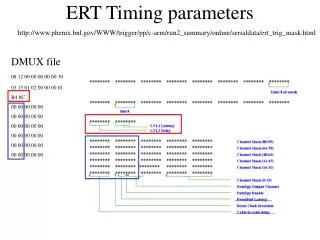
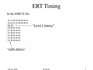
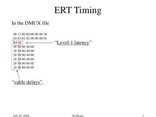
08 12 00 00 00 00 00 30 03 03 01 02 00 00 00 01 B4 8C 28 50 00 40 00 28 50 00 40 00 28 50 00 40 00 28 50 00 40 00 28 50 00 00 0C 28 58 00 00 0C. ERT Timing. In the DMUX file. “ Level-1 latency ”. “ cable delays”. Vince’s lecture. t. EMCal,RICH signals. ERT clock Cable to cable.

ERT Timing
E N D
Presentation Transcript
08 12 00 00 00 00 00 30 03 03 01 02 00 00 00 01 B4 8C 28 50 00 40 00 28 50 00 40 00 28 50 00 40 00 28 50 00 40 00 28 50 00 00 0C 28 58 00 00 0C ERT Timing In the DMUX file “Level-1 latency” “cable delays”. K.Okada
Vince’s lecture t EMCal,RICH signals ERT clock Cable to cable cable delays RBIB input Level-1 Latency (ROC by ROC) GL1 Global timing tune MiscWrite serial string ( ROC by ROC) GTM (Whole arm) K.Okada
Timing Adjustment The procedure might be the following. • Confirm the EMCal, RICH signals are in the middle of ERT clock. • Using RBIB input signals in scope, see the both edge by changing • the timing. (You can use any of GTM, MiscWrite, cable delay) • Then the next step is Level-1 latency adjustment. Check the data • taken with different setting. K.Okada
Example in Run4 The next slides show the result of time scan performed on January 19, 2004. I just changed “Level-1 delay”. Run delay data-entry GL1-entry 109704 +30 yes yes 109702 +20 yes yes 109701 +10 yes yes 109714 -10 yes yes 109715 -20 marginal yes 109716 -30 no yes K.Okada
So the current timing diagram must be like this RBIB input 10ns~20ns Level-1 Latency Am I correct? K.Okada
08 12 00 00 00 00 00 30 03 03 01 02 00 00 00 01 B4 8C 28 50 00 40 00 28 50 00 40 00 28 50 00 40 00 28 50 00 40 00 28 50 00 00 0C 28 58 00 00 0C ERT Time Scan (Jan 19) In the DMUX file “Level-1 latency” wasn’t changed. Several runs with different “cable delays”. See the ERT2x2 entries. K.Okada
Runs east west Default : 28 50 : 00 50 +10ns : 50 50 : 28 50 : 109701 +20ns : 78 50 : 50 50 : 109702, 109703 +30ns : A0 50 : 78 50 : 109704 -10ns(1) : C8 C0 : A0 C0 : 109705 -20ns(1) : A0 C0 : 78 C0 : 109712 -30ns(1) : 78 C0 : 50 C0 : 109713 -10ns(2) : C8 D0 : A0 D0 : 109714 -20ns(2) : A0 D0 : 78 D0 : 109715 -30ns(2) : 78 D0 : 50 D0 : 109716 • To set minus value, I used anti-polarity. Since I was not sure that • which way the polarity twitch moves, I tried two ways. • Subtract 1 clock ticks. –10=+53-106 + 40. • (2) Without any clock tick movement. –10=-53+40. • From the continuity, (2) seems to be the right answer. K.Okada