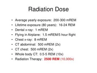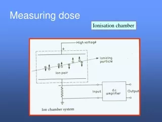
Total Dose
Total Dose. Recombination, Transport, and Trapping of Carries. GSFC Total Dose Facility. Example TID Static Bias Board Supports In Situ Testing. MIL-Std-883 Method 1019.5. Annealing allowed for parametric failures; not for functional failures. 1019.5 also allows for low dose rate testing.

Total Dose
E N D
Presentation Transcript
MIL-Std-883 Method 1019.5 Annealing allowed for parametric failures; not for functional failures. 1019.5 also allows for low dose rate testing.
Lab Instrument 1 Lab Instrument 2 Lab Instrument 3 Lab Instrument 4 Second Generation System - Overview WWW TID Chamber Building TID Chamber DUT “K-labs” GPIB GSFC network “rk” Server “Stupid” PC Test Control PC
Isolation Device Input Charge Pump Input Buffer Charge Pump andIsolation FETs from Wang, et. al.
In Situ Functional Testing Note: Some cases showed failure at less than 20 mA current with current jumps of 6-8 mA.
TID vs. Product Lifetime Device Technology (µm) Total Dose Lifetime A1020 2.0 > 100 krad( Si) 1988-92 A1020A 1.2 ~ 100 krad( Si)* 1991-95 A1020B 1.0/0.9 < 20 krad( Si) since '93 A1020DX 0.5 N/A - * Variable -some lots higher, some lower from Wang, et. al.
TID Testing Results • 0.60µM OTP PROM Technology • TID evaluation performed on XQR1701L • device parametric shifts affected decoder speed • field oxide leakage determined TID of 60krads • device fully functional at end of dose • no data loss/gain as a result of TID • 100°C anneal fully restored device • room temp anneal showed no rebound
In Situ measurement of Propagation Delay Real-time Digitized Input and Output Waveforms Before irradiation : tPD = 135ns After accumulating 90 krad : tPD = 260ns
VCC Ionizing Radiation Control Gate ONO Tunnel Oxide Floating Gate Source Drain Data Path Total Dose Effects on FLASH Switch • Ionizing radiation discharge the floating gate • Increase ON-state NMOS transistor resistance, increase RC delay in the data path • Increase OFF-state NMOS sub-threshold leakage, increase ICC