Fast Real-time SANS Detectors
200 likes | 391 Vues
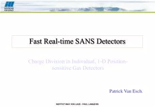
Fast Real-time SANS Detectors. Charge Division in Individual, 1-D Position-sensitive Gas Detectors. Patrick Van Esch. Project. Goal: fast real-time detector for small angle scattering. Main specifications: > 2MHz at 10% dead time (actually: only 50 KHz ). Resolution 128x128 on 1 m 2.

Fast Real-time SANS Detectors
E N D
Presentation Transcript
Fast Real-time SANS Detectors Charge Division in Individual, 1-D Position-sensitive Gas Detectors Patrick Van Esch.
Project. Goal: fast real-time detector for small angle scattering. Main specifications: > 2MHz at 10% dead time (actually: only 50 KHz). Resolution 128x128 on 1 m2. Efficiency ~ 75 % at 5 Angstrom. Good gamma - neutron separation. 5 microseconds time resolution for thermal neutrons Approach: 128 individual linear PSD. Charge division per PSD. People Bruno Guerard (detector group) Roland May (D22 responsible) Alexandre Sicard (PhD. student) Jean-Claude Buffet (mechanician) Frederic Millier (electronician) Patrick Van Esch (detector group) SANS-2MHz Millennium Project
Linear PSD detectors. 5 prototypes made by Reuter stokes. 7.12 mm active diameter. 7.95 mm mechanical outer diameter. 1 meter long. About 10 bar He-3 gas. Principle of Detector. Commercial 1 inch detector
Resistive Charge Division Johnson current noise Resistive anode wire 5.6 KOhm Event current 0.5 pC Up to 500ns Current noise i1 Current noise i2 Voltage noise v1 Voltage noise v2 Transimpedance preamplifier 2 Transimpedance preamplifier 1 Peak detection And ADC Gaussian Shaper 2 Gaussian Shaper 1 Baseline correction 2 Baseline correction 1
Principle of Resistive Charge Division Charge Q collected at both ends divides in A and B when wire length is L, distance of impact from A is x, wire resistance is R and preamplifier impedance is Z. Extraction of position information: the fraction (A-B)/(A+B) codes the position in the interval (-1,1), reduced by the dynamic range. Need for very low impedance (virtual ground).
Electronic Noise and Position Resolution White current spectral noise densities seen by both amplifiers at the input are correlated. The output R.M.S. voltage noise can be calculated from the input current noise spectral density. In the case of white noise, this simplifies to a factor related to the transimpedance function. These voltage noise values can be propagated in the position calculation, resulting in the position resolution due to electronic noise.
Resistive charge division. In contrast with capacitive (single ended) detectors: Faster shaping gives better S/N. Limited by overall conductance of wire (Johnson noise). Limited by integration time. Gaussian shaping. Best compromise between: Time domain pulse width. Frequency domain noise bandwidth. Implementation as 4th order pure pole active filter, about 1MHz bandwidth. Unipolar pulse shaping: Less dead time. But shift in baseline ! Baseline correction: Averages baseline over several microseconds (eliminating noise). Corrects input signal with that amount. Reduction with a factor less than 1/10 of the initial baseline shift. No visible added noise. Analogue Signal Processing
Prototype Primary Charge • HV bias: 100 V. • Integration time: 10 microseconds. • Using FET entry amplifier. • Allows us to estimate absolute gain of detector.
Spectra 1300 V 1100 V 1400 V 1500 V
Absolute Gain 1 inch detector 8 mm Prototype
Numerical application This results in a F.W.H.M. resolution of 5.5mm in the middle and 6.2mm on the borders.
Estimated dead time: 770 nanoseconds no extra dead time due to detector effects Implication for count rates (10% dead time correction): 130 kHz per tube SANS - 16.6 MHz Count Rate Issues
Large beam (35 mm FWHM) at about 100 KHz With and without a Cd sheet in beam length Spatial ‘resolution’ obtained ~9mm FWHM over entire length of detector. Reasonable upper estimate of true spatial resolution Spatial resolution at high count rates
The upper part of the spectrum suffers a degradation at high counting rates. This does not impair significantly the detector performance. Spectral behaviour at high count rate
Scan along anode with narrow beam Very stable efficiency all over the detector Transition zone only about 4 mm ! Efficiency Along Detector
Linear PSD based on the principle of resistive charge division offer great potential for building fast, large-scale neutron detectors. Resolution below 1cm at high count rates (>100kHz) can be obtained (6mm at low count rates). Very good linearity and uniformity. Electronics now exploits fully the potential of the detector. This opens up the possibility to have time resolution of the order of tens of microseconds. Conclusion