Download
1 / 38
380 likes | 399 Vues
This presentation provides an overview of the fast-timing applications in the context of International Linear Collider (ILC) detectors, including the need for high precision, reliability, and robustness. It discusses the role of particle flow paradigms, temporal calorimetry, and time-of-flight systems in improving event reconstruction and particle identification.

E N D
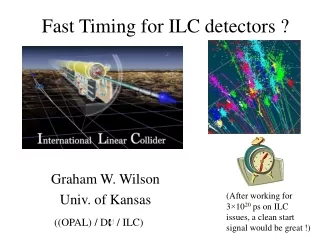
Fast Timing for ILC detectors ? Graham W. Wilson Univ. of Kansas (After working for 3×10²⁰ ps on ILC issues, a clean start signal would be great !) ((OPAL) / D / ILC)
Outline • Brief Overview of ILC from detector perspective • Consideration of fast-timing applications in the ILC context • Some directions to consider
Basics on ILC Physics and Detector Issues • Bunch structure: something like TESLA TDR. • (Dt)BX ≈ 337 ns. • 2820 bunches per bunch-train. 5 bunch-trains/s. • sz= 300mm
Event rates 14,100 BX/s
The Nature of e+e- Physics with ILC • Flexible (can really experiment) • s adjustable • Beams are highly polarizable • e- for sure (80-90%). e+ very likely (40-60%) • e-e- option. Perhaps gg, eg. • Clean • Signals can be extracted from background with relative ease and high efficiency • Kinematic Constraints • Beamstrahlung degradation comparable to initial-state radiation • Complete • Detection of individual particles over close to 4p • Calculable with High Precision • Excellent and valued work by a few theorists. Leads to good understanding of S and B. • Triggerable • Actually, no trigger required at all ! • Normalizable • Precision of few ‰ achievable
ILC Physics and Detector Issues • Rather clean environment. • No L1 trigger needed. Minimal multiple interactions. • Emphasis on measuring complete events (tracks, photons, neutral hadrons, missing ET) • the focus is on easily integrable, and robust detector technologies which will just work, and hopefully work really well, with high precision, reliability, redundancy and robustness. • R&D needed for improvements in precision and to validate new concepts. • High granularity, hermeticity, low-mass tracking. • Particle-flow paradigm for reconstructing hadronic jets promises circa 30%/E type resolution per jet. Main detector designs are “going with the flow” with ECAL and HCAL inside coil. • Constrains opportunities for additional PID like devices, but also offers opportunities. • Bubble-chamber like reconstruction of complete events. • eg. temporal calorimetry ??
Several slides stolen from recent seminar by Mark Thomson. http://ilcagenda.cern.ch/conferenceDisplay.py?confID=1279
High B-field required to wrap-up beamsstrahlung pairs. Important for vertex tracker and forward hermeticity Note: TPC drift time is 55 ms.
Is TOF and/or PID important for particle flow? Charged energy residual with average mass hypothesis TOF has potential for resolving some confusion in the calorimetry. Positive time ID of photons. Use time differences caused by bending in field to distinguish clusters originating from charged / neutral clusters ? Useful for eg K-/ K0L discrimination ? Particle-by-particle jet reconstruction systematics probably demand good control of p/K/p particle fractions. Most particles in energetic jets are still soft .. Contribution of charged-track mass ignorance to overall event energy at Z0. s = 0.35 GeV equivalent to 3.7%/E (NOT COMPELLING FOR TOF!, especially given other tools like dE/dx)
DT for 1.5 GeV pT tracks at cosq=0, for B=4.0 T, R=1.7 m pi : 0.59 ns K : 0.89 ns p : 1.68 ns DT for 3.0 GeV pT tracks at cosq=0, for B=4.0 T, R=1.7 m pi : 0.12 ns K : 0.19 ns p : 0.39 ns Temporal calorimetry for particle flow ? Idea: Use time difference between b=1 straight line (photon) and b<1 curved track (charged pi, K, p) OLD SLIDE Loopers have pT = 1.02 GeV here. (OLD) Conclusion: of order 100 ps resolution needed for time differences of the primary particle to be useful => looks impractical I hope today to be convinced to revise this old conclusion.
Additional path-length for charged particles 3.3 ns (for b=1) 330 ps 33 ps 3.3 ps (Maybe high B-fields aren’t all bad for TOF enthusiasts)
Some Recent Classic Time-of-Flight Systems at Colliders Detector B-field (T) R (m) L(m) Nbars DT (ps) Medium • OPAL 0 (0.4) 2.4 6.8 160 350 4.5cm NE102 • CDF 1.4 1.4 2.9 216 120 4 cm BC408 • BELLE 1.5 1.2 2.6 128 100 4 cm BC408 (outside 2X0 NC coil + pressure vessel) Length-scales (and time-scales of the scintillation emission) not suited to sub 100-ps resolution. At LEP, only experiment with genuine TOF was OPAL. DELPHI and L3 had some external cosmic vetoes. OPAL TOF mainly used for triggering and some “niche” physics, NOT p/K/p ID. CDF and BELLE TOF raisons d’etre: B-physics (low-pT)
Example: Photon Timing OPAL: e+e- → nng st = 250 ps Eg > 1.5 GeV 2X0 helps here ! Points: photon candidates Histogram: electrons
Particle ID • Most LEP experimenters would be very hard pressed to make a case for invasive particle ID solutions which take a lot of space, add lots of material, and in the end compromise the detector’s overall success. • The OPAL experiment, where I worked on the TOF system, took advantage of very good dE/dx, which made TOF with modest precision close to redundant from the PID perspective. • The TOF system was extremely useful and helpful in data analysis especially for triggering and bunch identification in the bunch-train era. • The TPC-based ILC detector(s) are likely to have rather good dE/dx, comparable to OPAL without the drawbacks (4-bar) and with the potential of using cluster-counting to do even better.
dE/dx Hauschild Hauschild P10 Gas Solid = 1 atm Dashed = 4 atm Note the cross-over regions where dE/dx is blind. These are relatively narrow in p especially the 1/b2 ones
dE/dx Separation Power CDF TPC-based ILC detectors are likely to have dE/dx performance similar to or better than OPAL. TOF devices can help in the cross-overs. High B-field => emphasis on loopers, low-pT (e/K, e/p, p/K, p/p)
Time-of-Flight in Barrel Region Tracks with pT < 0.96 GeV loop … Endcap TOF ? p/p (e/p) K/p (e/K) p/K e/p e/m m/p Low momentumm/p is an interesting new capability which psec-TOF could address !
One way of implementing TOF targeted at the 50 ps regime ? • Scintillating fiber outer tracking layers (after TPC) for linking tracks to ECAL. • Detector could provide: • Outer reasonably precise space points very close to ECAL. • Several TOF measurements. • Bunch-of-interest ID. • Independent solid-state tracking device for aligning TPC, with complementary r-z measurement capability. • Can be implemented in a non-invasive manner in a high B-field region
Scintillating fiber tracking layers f=835mm D fiber tracker doublet layer With the advent of SiPM’s with 1mm2 area, the challenges of the above detector are avoided. Allows direct coupling of Sc. fiber to high gain photo-detector in B-field at room temperature. D: average light yield of 8 photo-electrons per MIP, using system with 1.5% light collection efficiency (including trapping, reflector, transitions, attenuation in scintillator, attenuation in > 8m wave-guide, VLPC quantum efficiency). With same fibers and 1.6m length expect 50 photo-electrons (L+R) with 65% PDE MPPC-100. Standard fibers l > 3.5m
SiPM’s • Noise not a major issue with coincidences (or 1.5pe threshold) • Dynamic range (100 pixels) and PDE of 65% of MPPC-100 is well adapted to 1mm fibers. • TTS (FWHM) = 250 ps Also SensL
32 layers of fibers arranged on 8 support-cylinders. Within each super-layer, 2 layers for axial, 2 for stereo. Material budget total approx 9% X0. One super-layer = 1.1%X0
Fibers for TOF. Are you crazy ? n(core) = 1.59 n(clad1) = 1.49 n(clad2) = 1.42 Propagation only Light trapping efficiency is small, but the ones that are trapped are the fast ones. Time spread per m: Single-clad fiber: 390 ps/m Multi-clad fiber : 640 ps/m Scintillator/air-gap (BELLE) : 1540 ps/m Need very fast scintillating fiber, if this is to be the major effect though. BC-422Q0.5 (PVT) has 360ps FWHM at 19% anthracene light output.
Applying to LDC ? Could apply as a thin outer-tracking envelope in the barrel with r-f and r-z doublet planes mounted either on the ECAL barrel or the TPC field cage. Could also apply as a thin outer-tracking envelope in the endcap with x-z and y-z doublet planes mounted on the ECAL endcap In both locations, time-of-flight (TOF) capability appears feasible, especially if both ends of the fibers are read-out.
Measure r-f Would prefer 3 modules in z. For timing performance probably best to split in 3. Measure r-z Could also imagine a x-u plane with 45 degree angle Note: endcap is a region which is likely to be the weak-link of particle-flow especially for loopers, and this may be an area where this kind of detector could contribute
With sufficient light budget, doublet layer leads to 4 ≈ well defined regions per pitch unit (A, B, C, D) with approximately the same width. So intrinsic resolution is about (pitch/4)/12 assuming no cross-talk and high efficiency. With only a few layers, need redundancy in case of single dead channels. So prefer to read-out both ends of the fiber IF it can be done easily. This lends itself to a classic TOF-like application too. Doublets 101 pitch 2 4 3 1 A B C D The D scheme: pitch=960mm, leading to sr-f = 90 mm (test-beam)
Achievable Performance ? • Assuming doublet arrangement for each plane with redundant readout, expect 100% efficiency per coordinate, and high efficiency for precise pitch/4 effective cell size. • Geometries with vernier-style readout can be considered using the measured light output per layer. D basically achieves pitch/10 = 100 mm for these 775 mm active diameter fibers with only 8 photo-electrons per MIP. Ultimate performance limited by fiber placement errors in the ribbon at the ≈ 20 mm level For LDC, shorter fibers, flat planes, no light-guides => estimate 80 mm resolution for both r-f and r-z (barrel) or for z-x and z-y (endcap). Square is probably best for this.
Timing Performance • Standard D radiation hard scintillator tdecay = 7ns. BCF-20 has tdecay = 2.7ns at 492 nm. • For each track could have on average about 6 time measurements each with about 20 photo-electrons. • Time resolution will depend on method and electronics. With the spread in effective propagation speeds due to photon emission angles and the 1600:1 aspect ratio of the fibers, I suspect a timing based on the arrival time of the earliest photo-electrons may be appropriate. • Another technique, would be to mirror one-end, and use a multi-hit TDC to time both the direct and reflected light. • Having several measurements with precision input from TPC will help control time systematics vs propagation distance. • Guess something like 250 ps easily achievable, probably more like 100 ps, and potential for improvement with R&D.
Channel Count • Barrel (r-f). 1600 doublets per octagon. • => 50 k fiber ends * n_modules = 150k (for n=3) • Barrel (r-z). 4400 doublets per octagon. • => 140 k fiber ends • Endcap (x-z). 1200 doublets per quadrant • y-z. 1200 doublets per quadrant • => Total of 38k fiber ends. • In total 333k fiber ends. (only 3.3% of GLD ECAL!) • So, may need to decide what level of redundancy, position precision and time resolution we can afford and need • But given developments in SiPM’s it is probably not a show-stopper.
Outer TOF/tracking layers • For about 1% X0, can envisage space points with resolution of 100 mm, time resolution of 100 ps, and minimized distance to ECAL. • Smaller fibers are feasible to 250 mm, but need multi-anode SiPM designed for smaller area …. • Can also envisage embedding such layers in parts of the calorimeters.
Other ways ? • Specialized TOF using thick tiles of either Cerenkov radiator or scintillator with direct light readout. • Gaps ? • Cost ? • Material ? • Radial space ? • Need strong arguments for super-precision if the only measurement is TOF, and it is done in a one-shot way. • ECAL timing layer is needed for some reactions eg. (single photons). Given instrumental backgrounds (halo muons, cosmics) I think a timing layer in the ECAL is extremely desirable for any detector). • Similar arguments also suggest a hermetic outer muon veto layer. • Easily integrable Cerenkov devices (eg fibers) could play a role in the calorimetry especially for measuring EM fractions in hadron showers. • Any advocates for “time-of-propagation” (using C-light arrival time to measure TOF + TOP which is itself dependent on the local Cerenkov angle)?
Conclusions • ILC detectors could and, I would argue, should take advantage of some of the possibilities for implementing fast timing at the sub-100 ps level in a strong B-field, IF they can be implemented in ways which clearly enhance the overall performance of a general-purpose detector. • I am intrigued by the possibilities in this domain, and very much welcome collaboration on some of these ideas.
frankyaug05 A radially staggered buildable analog calorimeter with exquisite granularity, with no cost optimization using Tungsten. B = 3T. With M. Thomson. Acknowledgements to N. Graf (W was cheaper in 05..) R(m) Nlayers X0 Active Cell-size (mm) EM Barrel 1: 2.10 10 0.5 Si 2.5 × 2.5 × 0.32 EM Barrel 2: 2.13 10 0.5 Si 10 × 10 × 0.32 EM Barrel 3: 2.16 20 0.5 Sc 20 × 20 × 2 HCAL: 2.255 50 2.0 Sc 40 × 40 × 2 Choices made based on current R&D work, driven by making a sensible, robust design with aggressive performance and minimizing Silicon area in a GLD-scale detector. Expect: sE/E = 11%/E at low energy 50 GeV photon