Fast Timing R&D
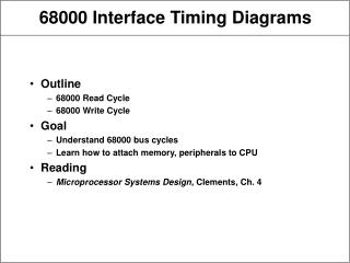
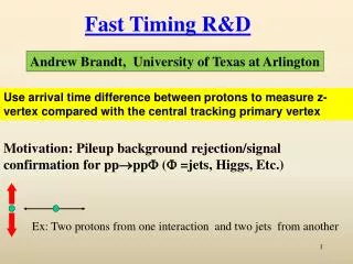
Fast Timing R&D. Andrew Brandt, University of Texas at Arlington. Use arrival time difference between protons to measure z-vertex compared with the central tracking primary vertex. Motivation: Pileup background rejection/signal confirmation for pp pp ( =jets, Higgs, Etc.).

Fast Timing R&D
E N D
Presentation Transcript
Fast Timing R&D Andrew Brandt, University of Texas at Arlington Use arrival time difference between protons to measure z-vertex compared with the central tracking primary vertex Motivation: Pileup background rejection/signal confirmation for pppp ( =jets, Higgs, Etc.) Ex: Two protons from one interaction and two jets from another
Requirements for an LHC Proton Timing System • 10 ps or better resolution at high luminosity • High efficiency and full acceptance • High rate capability (proton rates up to 5 MHz/pixel ) • Segmentation for multi-proton timing • Robust operation in high radiation environment 10 picosecond resolution is design goal (light travels 3mm in 10 psec!) gives ~x20 fake background rejection; originally considering 25 interactions per crossing, now designing for 50 interactions 2
QUARTID (QUARtzTIming Detector) proton QUARTIC concept: Mike Albrow for FP420 (R&D effort for diffractive Higgs at LHC) 2004 based on Nagoya Detector. photons Initial design: 4x8 array of 6x6 mm2 quartz bars , 8-12 cm long Isochronous—by mounting detector at Cherenkov angle, all light reaches tube at ~same time 1.4.1.1 1 2 3 4 MCP-PMT Proton is deflected into one of the rows and measured by eight different bars/detector with a micro-channel plate PMT. If t= 40 ps/bar need 16 measurements /row for 10 ps If t= 28 ps/bar need 8 measurements/row for 10 ps Increase #rows to minimize multi-proton and rate effects (pixelation)
Components of AFP Fast Timing Main components exist, and have been validated in pulser, laser, and beam tests
Lifetime Issues • Historically MCP-PMT’s have not been extremely robust, and are typically capable of operating only for a few hundred mC/cm2 before their performance (QE) degrades, presumably due to positive ions damaging the photocathode. • If operated at high gain without sensible pixelation, this amount of charge would be accumulated too quickly for the device to be useful • For low gain (5E4) and modest pixelation (4 equal rate bins), the lifetime presents a challenge:=23 impliesR=4 MHz/pixel and I=0.8A/cm2 resulting in an annual charge of 8 C/cm2/yr(with LHC year =1x10⁷s). This corresponds to Ldt=[23 (40 x 0.8) MHz] t/100 mb=80 fb-1. In other words, for every 10 fb-1 or so 1 C/cm2is accumulated. • Formed a collaboration between UTA, Arradiance, and Photonis to address these issues, partially funded by NSF SBIR
Brandt’s Ideal MCP-PMT e- Improved lifetime by x10-20 (3 main options) 1) Suppressed positive ion creation (Arradiance) 2) Ion Barrier keeps positive ions from reaching photocathode (Nagoya/Hamamatsu) 10 m pore EDR MCP for max rate ALD by Arradiance + + + + 3) Use Solar Blind photocathode (UV response to more robust) photon Funding for Solution 1 Increase cathode voltage to improve collection efficiency (UTA) Photocathode Photoelectron DV ~ 400V Dual MCP DV <3000V Run at low gain to reduce integrated charge (UTA) Gain <105 MCP-PMT Increase anode voltage to reduce crosstalk (UTA) DV ~ 400V Anode Reduce anode gap to reduce cross talk
Established in 2009 at UTA with DOE Advanced Detector Research,+Texas ARP funds, primarily to evaluate MCP-PMT’s for use in fast timing. • Relies heavily on the use of undergraduates • The PTL serves as a permanent test bed to study a myriad of subtle effects associated with picosecond timing beam splitter mirror LeCroy Wavemaster 6 GHz Oscilloscope filter MCP-PMT lenses laser Hamamatsu PLP-10 Laser Power Supply beam mode fiber mode Laser Box 1)Evaluate MCP-PMT and electronics with laser tests 2) Evaluate detector/full chain with test beam Early setup
MCP-PMT Rate and Current Conventional wisdom: need high gain for fast timing (but CW is based on single pe experience). From UTA laser tests timing is ~ independent of gain as long as Reduces current requirement by x10 to 20 • Anode Current = proton Rate Number of photo-electrons generated by each proton Gain charge • 4 MHz proton rate with 10 pe’s at 106 gain gives 6.4 µA in a 0.4 cm2 pixel or about 16 µA/cm2, several times what is possible!
MCP-PMT Cross Talk and TTS TTS=transit time spread Photons • Cross talk could correlate adjacent channels within a row and reduce expected N improvement • Cross talk can give a false signal in channel in adjacent row which distorts/biases time measurement if there is a second proton in that row t=38 ps Optical Crosstalk Photoelectron Recoil Rebound Recoil Pe Rebound Electrical Crosstalk (charge sharing) Anode 1 Anode 2
Cross Talk and other MCP-Issues Pedro Duarte, Masters Thesis on early test beam studies 2007 Ryan Hall UTA, Honors Thesis on cross talk 2010 Paul Pryor UG Thesis on Lifetime 2011 James Bourbeau, Honors Thesis on test beam 2013 -Currently have team of 6 undergraduates (10-20/hr/week/person) Have studied and will continue to study many features of MCP’s @PTF • Cross talk: Using a series of fibers with different path lengths to simulate proton arrival time, found that ~10% of pulse is collected in adjacent pixel due to charge sharing -improves resolution for pixels in same row and correlates pixels since light is in time -degrades resolution and biases time for pixels in adjacent row (on either side) for later arriving proton • Two protons in same pixel mixes time in complicated manner • After-pulsing and origins of lifetime issues • Forming a data-based simulation of MCP response to augment GEANT capabilities • Tuning cathode and anode voltage to maximize performance (increase collection efficiency and reduce cross talk for example)
Lifetime Issues • Our first lifetime tests on ALD tube got out to 2 C/cm2 with no loss • in QE but too resource intenstive, will start major new lifetime tests • this summer Lehman et al As of todayno loss in QE with Q>5 C/cm2!!! 10-20 improvement over typical tube 1C~10 fb-1; similar results reported buPhotek! Arradiance-Modified 10 m Planacon Hamamatsu ion barrier SL10
Wrap-up: Timing vs. Rate 5MHz (~2 µA/cm2) Concern: only small quantities of these special tubes have been produced, so yield is uncertain -> quote is 13 to 38 k$ 12 *Have demonstrated desired timing capability at 5 MHz (~largest desired rate) with a long life high rate 25 µm pore PMT! *a 10 µm pore version has about 3 times the current capability and should maintain timing well beyond 5 MHz *Development continues, Expect to be able to make a >10 C/cm2 tube, which would last 100 fb-1 or longer
Designing a Baseline Detector • Equal area detector bins are not in general a viable option due to rate and lifetime issues in the pixels closest the beam • Equal rate pixels do not easily map to MCP-PMT pixels • Smaller width pixels are better than larger ones, since if two protons are in the same pixel, neither one would be well-timed • A full acceptance detector will suffer from cross talk, biasing neighboring rows • To avoid this bias one needs to implement buffers between the rows • Implies a two detector option with offset bins is a reasonable solution
A Potential Design: Two Offset QUARTIDS Increasing M beam Large x proton In 2013 will use simulation laser tests and (August FNAL test beam) to optimize layout, test beam in Jan 2014 to validate final design and electronics Increasing x • Design considerations: • 1) full acceptance, efficiency, excellent timing expected ~10 ps • 8 to 10 rows with x =1.5 to 3 mm(x=distance of proton from beam) will • avoid multi-proton effects (>90% efficient) and keep rate/pixel under 5 MHz • to control current/lifetime issues (can also rotate tube 180 degrees x2 lifetime) • 3) Buffers (space between rows) to avoid cross talk between rows • Rows probably should have partial overlap for alignment
FNAL SiPM used in trigger and as reference counter (15 ps resolution when used in beam with quartz bar) New Test Beam Setup Jan 2012 @FNAL New Stony Brook amp cards plug directly onto PMT beam QUARTIC Prepared @UTA for easy alignment and versatility
Time difference between SiPM and 6 –bar Quartic average gives FWHM=47 ps (=20 ps) better than design goal! T958 DAQ 2 3 4 5 6 7 Avg Just your garden variety 20 channel, 20 GHz/ch, 40 Gs/s ch (point every 25ps) 500k$ LeCroy 9Zi scope! “Thanks for the loaner LeCroy!”
SiPM- Quartic 6-Bar Average CFD read out by SCOPE CFD read out by HPTDC t =19.5 ps t 26.2 ps 26.2 ps QUARTIC and SiPM signals amplified, sent to CFD, then to scope, calculate t(SiPM-Qi) and average over 6 bars. Repeat for HPTDC readout. Difference between the measurements is dominated by 16 to 18 ps resolution of SiPM HPTDC Extract QUARTIC resolution (6 bar) 14 to 15 ps including Q-HPTDC (Note: edge channels had different gain, not useful for this run)
Ultimate Timing System Resolution Currently at 12 ps (Fall 2012 Test beam) with only 6 bars, and that ultimate performance of this system is probably about 8 ps
Highlights of R&D • In umpteen test beams (7?) we have shown steady improvement, obtaining single quartz bar/PMT resolution of 20 ps in last one (for 2x6x140 mm and 5x6x140 mm) • This corresponds to a 6 bar resolution including prototype readout electronics of 12 ps! • We have developed with Arradiance+Photonis a phototube capable of >5 MHz proton rate/pixel that has been demonstrated to have lifetime > 5 C/cm2 expected to be good for >100 fb-1, including x2 from rotating tube, with further improvements likely • Have successfully modified SLAC PLL Clock circuit that had sub-ps jitter for AFP’s circumstances