Instruments – part 1
Instruments – part 1. www.lrn.dk/arnop.htm. ARNOP Flight Dispatch course. Magnetic compass. ARNOP Flight Dispatch course. North Magnetic Pole (2005) 82.7° N 114.4°. Magnetic Northpole. ARNOP Flight Dispatch course. Magnetic Northpole.

Instruments – part 1
E N D
Presentation Transcript
Instruments – part 1 www.lrn.dk/arnop.htm ARNOP Flight Dispatch course
Magnetic compass ARNOP Flight Dispatch course
North Magnetic Pole (2005) 82.7° N 114.4° Magnetic Northpole ARNOP Flight Dispatch course
Magnetic Northpole It wanders in an elliptical path each day, and moves, on the average, more than forty meters northward each day ARNOP Flight Dispatch course
Earth magnetism ARNOP Flight Dispatch course
Magnetic dip ARNOP Flight Dispatch course
Magnetic variation ARNOP Flight Dispatch course
Magnetic variation VARIATION WEST, MAGNETIC BEST, VARIATION EAST, MAGNETIC LEAST ARNOP Flight Dispatch course
Magnetic deviation ARNOP Flight Dispatch course
Deviation table ARNOP Flight Dispatch course
Magnetic compass Magnectic compass for an aircraft ARNOP Flight Dispatch course
Magnetic compass ARNOP Flight Dispatch course
Northerly Turning Errors: The result is a false northerly turn indication Compass errors Southerly Turning Errors: The result is a false southerly turn indication Acceleration error:When accelerating on either an east or west heading , the error appears as a turn indication toward north. When decelerating on either of these headings, the compass indicates a turn toward south. ARNOP Flight Dispatch course
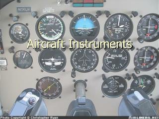
ADC: Air Data Computer Pressure instruments ASI: Airspeed Indicator VSI: Vertical Speed Indicator Machmeter Altimeter ARNOP Flight Dispatch course
Pitot / static system ARNOP Flight Dispatch course
Static port ARNOP Flight Dispatch course
Pitot tube ARNOP Flight Dispatch course
Pitot / static ports ARNOP Flight Dispatch course
Pitot / static ports ARNOP Flight Dispatch course
ASI Airspeed Indicator ARNOP Flight Dispatch course
ASI errors ARNOP Flight Dispatch course
ASI calibration The Airspeed Indicator is calibrated to ICAO ISA atmosphere Pressure: 1013,25 hPa Temp: +15C Density: Standard MSL ARNOP Flight Dispatch course
Speed definitions IAS: Indicated Air Speed CAS: Calibrated Air Speed (IAS corrected for installation and position error) EAS: Equivalent Air Speed (CAS corrected for compressibility error) TAS: True Air Speed (EAS corrected for density) ARNOP Flight Dispatch course
VSI Vertical Speed Indicator The vertical airspeed specifically shows the rate of climb or the rate of descent, which is measured in feet per minute or meters per second ARNOP Flight Dispatch course
Machmeter An aircraft flying at the speed of sound is flying at a Mach number of one, expressed as "Mach 1.0". ARNOP Flight Dispatch course
Altimeter ARNOP Flight Dispatch course
QFE / QNH The regional or local air pressure at mean sea level (MSL) is called the QNH or "altimeter setting", and the pressure which will calibrate the altimeter to show the height above ground at a given airfield is called the QFE of the field. An altimeter cannot, however, be adjusted for variations in air temperature. Differences in temperature from the ISA model will, therefore, cause errors in indicated altitude. ARNOP Flight Dispatch course
QFE / QNH QFE: Aerodrome elevation pressure(Altimeter indicate 0 ft height) QNH: QFE reduced to MSL according ISA (Altimeter indicate aerodrome elevation) 1 hPa = 27 ft ARNOP Flight Dispatch course
QFE / QNH ARNOP Flight Dispatch course
Height / Altitude Indicated height: QFE as datum Indicated altitude: QNH as datum True altitude: corrected for temp and pressure ARNOP Flight Dispatch course
Transition level / altitude ARNOP Flight Dispatch course
ADC Air Data Computer Modern aircraft use air data computers (ADC) to calculate airspeed, rate of climb, altitude and mach number. Two ADCs receive total and static pressure from independent pitot tubes and static ports, and the aircraft's flight data computer compares the information from both computers and checks one against the other. ARNOP Flight Dispatch course
A gyroscope is a device for measuring or maintaining orientation. This orientation changes much less in response to a given external torque than it would without the large angular momentum associated with the gyroscope's high rate of spin. Since external torque is minimized by mounting the device in gimbals, its orientation remains nearly fixed, regardless of any motion of the platform on which it is mounted. This stability increases if the rotor has great mass and speed. Thus, the gyros in aircraft instruments are constructed of heavy materials and designed to spin rapidly (approximately 10,000 rpm to 70,000 rpm). Gyro ARNOP Flight Dispatch course
Attitude indicator The purpose of the attitude indicator is to present the pilot with a continuous picture of the aircraft's attitude in relation to the surface of the earth. The figure to the right shows the face of a typical attitude indicator ARNOP Flight Dispatch course
HEADING INDICATOR: The heading indicator, shown in the figure to the right, formerly called the directional gyro, uses the principle of gyroscopic rigidity to provide a stable heading reference. The pilot should remember that real precession, caused by maneuvers and internal instrument errors, as well as apparent precession caused by aircraft movement and earth rotation, may cause the heading indicator to "drift". Heading indicator ARNOP Flight Dispatch course
Because the earth rotates (apparent drift) and because of small accumulated errors caused by friction and imperfect balancing of the gyro (real drift), the Heading Indicator will drift over time, and must be reset from the compass periodically. The HI cannot sense North like a compass. The HI must be realigned with the compass about every 10 minutes. You might say to yourself, "Why don't I just use the compass?". The compass can be very difficult to read because it wobbles around. The HI is more stable and easier to read, but it must constantly be realigned. Gyro drift ARNOP Flight Dispatch course
Some more expensive heading indicators are 'slaved' to a sensor (called a 'flux gate'). The flux gate continuously senses the earth's magnetic field, and a servo mechanism constantly corrects the heading indicator. These 'slaved gyros' reduce pilot workload by eliminating the need for manual realignment every ten to fifteen minutes. Flux gate ARNOP Flight Dispatch course
Non Precission Approach NDB – Non Directional Beacon VOR – VHF Omni-directional Radio range TACAN -TACtical Air Navigation ARNOP Flight Dispatch course
MDH / MDA A minimum descent height (MDH) or minimum descent altitude (MDA) is the equivalent of the DA for non-precision approaches, however there are some significant differences. It is the level below which a pilot making such an approach must not allow his or her aircraft to descend unless the required visual reference to continue the approach has been established. Unlike a DA, a missed approach need not be initiated once the aircraft has descended to the MDH, that decision can be deferred to the missed approach point (MAP). So a pilot flying a non-precision approach may descend to the minimum descent altitude and maintain it until reaching the MAP, then initiate a missed approach if the required visual reference was not obtained. ARNOP Flight Dispatch course
NDB Non-directionalbeacon NDBs typically operate in the frenquency range from 190 kHz to 535 kHz. ARNOP Flight Dispatch course
NDB Other information transmitted by an NDB Automatic Terminal Information Service or ATIS Meteorological Information Broadcast or VOLMET ARNOP Flight Dispatch course
ADF Automatic Direction Finder ARNOP Flight Dispatch course
ADF receiver ARNOP Flight Dispatch course
VOR VORs are assigned radio channels between 108.0 MHz (megahertz) and 117.95 MHz (with 50 kHz spacing); this is in the VHF (very high frequency) range VHF Omni-directional Radio Range ARNOP Flight Dispatch course
VOR receiver ARNOP Flight Dispatch course
VOR VHF Omni-directional Radio Range ARNOP Flight Dispatch course
VOR ARNOP Flight Dispatch course
DME Distance Measuring Equipment ARNOP Flight Dispatch course
1. VHF COM 1. • The frequency is on the STANDBY (right) side and then transferred to the ACTIVE (left) side with the TFR button in between. • 2. VHF COM 2. • 3. ADF 1. • The frequency can be set on both sides. The TRF switch is used to select the active side. • 4. ADF 2. • 5. SELCAL. • 6. Transponder and TCAS control panel. • 7. Center instrument and pedestal light switches. Aircraft control pedestal ARNOP Flight Dispatch course
TACAN TACAN in general can be described as the military version of the VOR/DME system. It operates in the frequency band 960-1215 MHz. The bearing unit of TACAN is more accurate than a standard VOR. TACtical Air Navigation ARNOP Flight Dispatch course