Electric Snowmobile
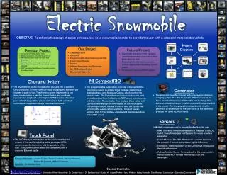
Electric Snowmobile. OBJECTIVE : To enhance the design of a zero-emission, low-noise snowmobile in order to provide the user with a safer and more reliable vehicle. . System Diagram. Motor Control. Previous Project Comprised of 20KW electric motor Motor mounted on solid aluminum frame

Electric Snowmobile
E N D
Presentation Transcript
ElectricSnowmobile OBJECTIVE: To enhance the design of a zero-emission, low-noise snowmobile in order to provide the user with a safer and more reliable vehicle. System Diagram Motor Control • Previous Project • Comprised of 20KW electric motor • Motor mounted on solid aluminum frame • 96V Battery Bank (eight 12V Lead Acid Batteries) • Batteries stored under seat compartment • Pulse Width Modulation Circuit controls transistor ON/OFF • IGBT (Insulated Gate Bipolar Transistor) controls armature current • Our Project • Charging Circuit • Generator • Programmable Automation Controller • Touch Panel Display • Sensors • Voltage Regulators for Electronics • 12v DC Auxilary Outlet • Mechanical Upgrades Future Project • Automatic charging of the batteries using the generator when the voltage levels drop too low • Charging with alternative systems such as regenerative breaking or solar panels • Emergency communication systems Charging System • The 12V batteries can be charged when plugged into a standard 120V wall outlet. In order to ensure equal charging, the batteries are charged in pairs of two. The charging system implements a two stage configuration in which a current limiter and a voltage regulator are employed. A Darlington NPN transistor is the focal point of both stages. Using diodes and resistors, both a limited current and a regulated voltage have been achieved. • Touch Panel • The LCD display is an interface for the user to monitor the systems of the vehicle including battery voltages, RPM, current drawn by the motor, and temperature of the IGBT. The panel is connected to the CompactRIO via a crossover Ethernet cable. • Sensors • Multiple sensors are used to provide feedback to the user: • RPM: This sensor is mounted near one of the gears of the DC motor. Every time a gear tooth passes the sensor a pulse is generated. • Current Sensor: This Hall Effect sensor is used to measure the amount of current being drawn by the DC motor. • Thermistor: The temperature of the IGBT circuit is measured through a thermistor. • Voltage Monitor Sensor: To keep track of the snowmobile’s various batteries, a voltage monitoring circuit was developed. • NI CompactRIO • This programmable automation controller is the heart of the monitoring system, it contains three modules: Digital Input, Analogue Input, and Analogue Output, which monitor the vehicle’s data. The Digital/Analogue input modules are used to read in values from the batteries, RMP sensor, current sensor, and thermistor. The controller then analyzes these values with LabVIEW, and displays the information on the touch panel. The analogue output module is used to send out signals that will notify the user of certain warnings. This port powers warning LEDs for low battery voltages and high temperature of the IGBT circuit. • Generator • The generator provides the user with an emergency backup charging system. It is able to provide 3KW of power for 2.5 hours under full load and will allow the user to charge the batteries enough to return to safety and avoid being stranded in the woods. The charging system plugs directly into the generator as a substitute for the wall outlet as the generator provides the same AC input signal. Group Members: Lindsey Chiron, Roger Gauthier, Patrick Hingston, Parker McDonnell, Michael Swanson Advisor:Dr. Gordon Kraft Special thanks to: ◊ University of New Hampshire ◊ Dr. Gordon Kraft ◊ Dr. Barbara Kraft ◊ Lesley Yu ◊Adam Perkins ◊ Joyce Perkins ◊ Kathy Reynolds◊ Dan Mooney◊ Substructure ◊ Generator Connections ◊