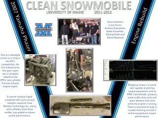
Clean Snowmobile Team
PIGGYBACK DIVISION MATTHEW MENARD CRAIG FORTIER NOISE VIBRATION AND HARSHNESS DIVISION JOSHUA AYERS DANIELLE MCCAFFERTY NOAH WRIGHT DUSTIN MCCANN COMPOSITE COWLING DEVELOPMENT DIVISION MATTHEW BODWELL EVAN MERRIT CHRISTOPHER HILL JESSE MORIN CONCEPT CHASSIS DEVELOPMENT DIVISION
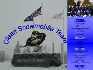

Clean Snowmobile Team
E N D
Presentation Transcript
PIGGYBACK DIVISION MATTHEW MENARD CRAIG FORTIER NOISE VIBRATION AND HARSHNESS DIVISION JOSHUA AYERS DANIELLE MCCAFFERTY NOAH WRIGHT DUSTIN MCCANN COMPOSITE COWLING DEVELOPMENT DIVISION MATTHEW BODWELL EVAN MERRIT CHRISTOPHER HILL JESSE MORIN CONCEPT CHASSIS DEVELOPMENT DIVISION COMPOSITE CONCEPT CHASSIS THOMAS LAMONTAGNE MICHAEL BOWERS TUBULAR METALLIC CONCEPT CHASSIS DARRELL FLAGG OTIS CLAPP BRIAN WILD MATTHEW WYATT Clean Snowmobile Team SLED BEAR
PIGGY BACK DIVISION During the first year in the Clean Snowmobile Challege in 2004 the emissions team decided to add a catalytic converter to the 4 stroke 660cc Arctic Cat engine that they were using. Last year the emissions team decided after a serious of tests to leave the catalytic converter intact and try to improve the sled through a microcontroller unit. This first microcontroller unit only used a single reading from a wide band O2 sensor to control the Air Inlet Temperature (AIT). AIT was altered inside the piggyback depending on the single input to change the AIT that the sled ECU was reading. This in turn controlled the Air to Fuel ratio (A/F). When the A/F ratio is running at a rich mixture the amount of CO, and HC are reduced. When the mixture is running at a lean mixture the amount of NOx emissions are reduced.
PIGGY BACK DIVISION This year we took the piggyback a step further. We went ahead and added a throttle position sensor (TPS) as the second input to the piggyback in hopes to better control the A/F ratio from idle to wide open throttle. The control of the A/F mixture can be accomplished through the use of a “piggyback” electronics system with the help of analyzers such as a wideband O2 sensor, throttle position sensor, dynamometer, and exhaust gas analyzer. This system will change information going into the Engine Control Unit or ECU. The main purpose of the ECU is to determine the pulse width of the fuel injectors. Pulse width is defined as how long the injectors stay on. The pulse width is determined by sensors which act as inputs to the ECU. The ECU looks at the incoming signals, then through programming logic and data tables determines the appropriate pulse width for the situation
PIGGY BACK DIVISION The 2006 Piggyback control unit success achieved the goals of reducing the emissions of the 2003 Arctic Cat 4 stroke snowmobile. Although it was not able to provide significant reductions that exceeded the 2005 piggyback, for the full throttle range, it did greatly reduce the emissions that were being produced during the sled idling. These were the highest emissions of the sled during the competition last year. With the proper inputs this piggyback would make for a quality addition to any stock sled in order to consistently with lower emissions, making it an excellent addition to a Snowmobile Conversion Kit.
NOISE VIBRATION AND HARSHNESS DIVISION This project focuses on the improvements to this sled in the noise vibration and harshness area. Initial benchmarking of the performance of our sled will be required, along with testing of the effect of a range of standard and new modifications. Exhaust modifications will not necessarily be emphasized, instead the drive train, mechanical noise, induction and other noise sources will be most likely to be the source of significant gains in noise reduction. This test apparatus was built to analyze insulating material. A six-inch diameter speaker is attached to a PVC tube one meter in length. The insulating material to be tested is inserted at the opposite end of the tube and a microphone (shown in picture) or sound level meter is mounted in a PVC shell immediately after the material. A frequency generator provides the signal to the speaker that emits a single frequency. The material response is then displayed by either the sound level meter or an oscilloscope. Five materials were chosen from the material matrix and a one third octave band analysis was performed. A sample of each material was put into the acoustic test tube and bombarded with sound at each individual frequency. An A-weighted sound level meter recorded the sound pressure level at each frequency. From this analysis, it was determined that the best material to use for our cowling insulation was material 7, Cotton Echo Eliminator with High Density Layer, made by Acoustical Surfaces, Inc.
NOISE VIBRATION AND HARSHNESS DIVISION During baseline sound runs for the sled, it was determined that the left side of the sled was consistently louder than the right side. Since the left side of the sled is the clutch side, the clutch was designated a significant noise source. To combat this problem, an enclosure was designed and built to acoustically isolate the clutch compartment. Complete isolation brought up the problem of possible overheating and failure of the clutch belt and so a dedicated blower and ducting system were added. The blower is controlled by an adjustable temperature control unit and provides 60 cubic feet per minute of air directly to the clutch compartment. This flow is circulated through the clutch case and is then ported to the back of the engine compartment to provide auxiliary engine cooling.
NOISE VIBRATION AND HARSHNESS DIVISION Several modifications were made to the rear suspension system. Arctic Cat suspensions use one of the runner cross-members as the rebound stop for the rear arm of the rear shock. This metal-on-metal contact is a significant noise source. A “bumper” made of a high durometer motor mount material has been added to this system to transform the high frequency vibration of this contact point into very low frequencies and heat energy. Another significant noise source on the suspension is the friction contact of the track on the runners. To decrease this noise source and help decrease wear on the runners, a total of eight idler wheels were added in two sets of four. Each of these sets spans the full width of the track and together they provide an even quieter alternative to the already quiet Arctic Cat Quiet Track.
COMPOSITE COWLING DEVELOPMENT DIVISION University of Maine Mechanical Engineering M Senior Design 05-06 Goals Motivation • Improve quality of hood • Decrease overall weight of hood • Improve rigidity and optimize fiber orientation • Increase hood clearance over previous years The original cowling no longer fits due to under hood clearance issues brought on by the addition of emission control hardware. Two replacement hoods have been built previously and yielded mixed results. Neither hood looked particularly appealing and both had fitment and performance issues. And, needless to say, neither hood was satisfactory to represent the Maine Clean Snowmobile Team.
COMPOSITE COWLING DEVELOPMENT DIVISION University of Maine Mechanical Engineering M This Years Achievements Senior Design 05-06 It can be seen in the pictures that this years cowling is a drastic improvement over previous years and even over the original stock cowling. This years hood was designed to better clear the muffler under the hood while simultaneously improving looks and bettering the fitment. The new cowling has a far more impressive appearance, boasting the carbon fiber look. As expected, overall rigidity is up due to the material strength gained by choosing carbon fiber over glass fiber, and the increase in the total amount of material that makes up the cowling. This years hood did not show a significant weight decrease because most of the time had to be spent on creating the mold and learning the proper fabrication procedures. Learning the proper procedures helped ensure professional quality. The team built this first pass cowling on the safe side, figuring it is better to have cowling that could be depended on rather than ending up with a few pieces that once were a cowling.
University of Maine M Mechanical Engineering COMPOSITE COWLING DEVELOPMENT DIVISION Future Work The developments made this year will allow future teams to concentrate on performing a more in depth stress analysis and lay-up optimization. This, more in depth design approach and better utilization of various core materials will allow the overall strength and rigidity to remain at their current levels while weight is reduced. Gaining overall efficiency thorough weight reduction by using modern engineering materials is and will be a focus of the Maine Clean Snow Mobile Team.