Shutdown plans for the FPIX
170 likes | 300 Vues
This document outlines the detailed shutdown plans for the FPIX detector at the University of Colorado, Boulder. Key tasks include purging cooling lines, removing and re-cabling components, replacing fragile silicon tubing with robust alternatives, and fixing various signal issues reported during operation. Improved humidity monitoring and the installation of a cold finger for temperature stabilization are emphasized. Ensuring reliable performance and achieving optimal thermal contact are critical objectives as the FPIX undergoes transportation and re-commissioning processes.

Shutdown plans for the FPIX
E N D
Presentation Transcript
Pixel General Meeting Shutdown plans for the FPIX Mauro Dinardo University of Colorado – Boulder, USA 27/01/2009
Work needed to be done on FPIX • Purge cooling lines • Un-cable & removal BCM • Un-cable BPIX pipes & power cables • Un-cable & removal FPIX • Transport FPIX to Meyrin building 186 (same place where I performed the commissioning of FPIX – everything is ready to host FPIX): • Substitute current Silicon tubes with more robust Silicon tubes which can withstand higher pressures • Fix the broken 6% • Put the cold finger to stabilize the AOH temperature during operation • Improve humidity monitor • Quick checkout (particular attention to sectors with apparently flaky HV connection and high baseline drift) • Photogrammetry • Transport FPIX back to P5 • Re-insert & re-cable FPIX • Re-cable BPIX power cables and pipes • Re-insert & re-cable BCM
Silicon tube replacement • Silicon tubes have been used inside the forward pixel detector to make the connection between the Aluminum pipes and the Half-Disk hose barbs • They need to be replaced with more robust tubes (same as those used by BPIX): • Current Silicon tubes are rated up to 1.7 bars • New Silicon tubes are rated up to 10 bars the limit will set by something else (Aluminum pipes and brazed cooling channels) will be able to run at 2.4 barg instead of 1.9 barg (big difference in terms of effectiveness of establishing flow)
Fix for the broken 6% • To be repaired: • BmI (HC-Z1) – Disk 1 – Blade 1 – Panel 2 – Plaquette 2 (2x4) Broken HV wirebond (8 ROCs) • Broken during transportation or insertion • Needs from FNAL: 3L panel • BmI (HC-Z1) – Disk 1 – Blade 10 through 12 Short on HV outer radius (93 ROCs) • Occurred ~1 month after installation (3/9/2008) • Needs from FNAL: 3R and 4L panels and –Z-In adapter board • Problem 1: obviously located on the panel • Problem 2: from measurements of resistivity it can be located at the level of the power filter board or on the power cable
Fix for the broken 6% • To be repaired: • BmO (HC-Z2) – Disk 1 – Blade 9 – Panel 2 Low analog signal amplitude (24 ROCs) • Occurred ~1 month after installation (11/9/2008) • Needs from FNAL: 3x panel and –Z-In adapter board • BmO (HC-Z2) – Disk 2 – Blade 4 through 6 Short on digital voltage (135 ROCs) • Occurred ~10 days after installation (11/8/2008) • Needs from FNAL: 3x and 4x panels and -Z-Out adapter board • Problem 3: is likely located at the TBM level • Problem 4: from measurements of resistivity it can be located at the level of the adapter board or on the panels
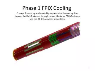
AOH cold finger and humidity monitor improvement • We want to put a “Cold fFnger” to perform a thermal contact between the AOHs and the cooling pipes in order to better stabilize the temperature during operation: • We studied the best design to implement … see next sides ! • The humidity reading at P5 has been difficult to interpret ! • We convinced ourselves that there was a pretty big leak inside the pixel volume that didn’t allow us to have a dew point below -8 on +Z-side and below +2 on the –Z-side. • We performed tests with the pilot run detector at TIF (docdb #2347) in order to better understand our HMX calibrations and the data that we measured at P5: • We should place the RTD much closer to the HMX • We should place the HMX in a spot which has a small temperature gradient: far from heat loads and heat sinks • We should follow up the work that is being done by Paolo&Machi in order to put reliable dew point meters with which we can cross check our HMXs
Origin of the Problem (e.g. Run #67838) FPIX – FED36 – BmO – ROG1-2 FPIX – FED37 – BmI – ROG1-2 BPIX – FED00 BPIX – FED12 BPIX has better stability and uniformity with time Within the hypothesis that the FED automatic baseline correction is working properly, the backend readout system can tolerate +/-3°C temperature variation (+/-150 ADC counts)
Pyrolytic Graphite: 5 Layers (500 μm) • Pyrolytic Graphite Sheets (PGS): • density: ~1 g cm-3 (= 1/9th of the Copper) • thermal conductivity: 600-800 W m-1 K-1 along the plane and 15 W m-1 K-1 perpendicular to the plane We made a “sandwich” of: ultra thin Kapton foil (for electrical insulation) + 5 foil of PGS, total thickness 500 μm (for heat removal) + G10 (to keep the PGS in contact to the AOH PCB) Problem: delamination of the foils (PGS is electrically conductive) a small vacuum cleaner should be used during installation
Pyrolytic Graphite: 5 Layers (500 μm) + encapsulation • Reference condition: without Cold Finger • In the Pilot Run Detector there are two portcards = two AOHs: • Black lines: first AOH • Colored lines: second AOH • Oscillations due to the conditioning of the clean room: +/-1° • With Cold Finger • Black lines: AOH with cold finger (500 μm) + encapsulation • Colored lines: AOH with cold finger (200 μm) The stability is improved by ~70% and the uniformity within the channels is very good
HMX Placement Scenario • Attached to the fibre bundles. Easy also for an Honeywell sensor • Close to the disk in the center. Not so easy for an Honeywell sensor • Attached to the end-flange. Not so easy for an Honeywell sensor
Aside work • Substitute the rear foot on all the four half cylinders: Greg Derillo • Check for high baseline drift: • BmO-DISK1-ROG1 (FED36 chn. 1,6) serious • BmO-DISK2-ROG1 (FED36 chn. 10,12) serious • BpI-DISK1-ROG1 (FED32 chn. 1,2) less serious • BpI-DISK2-ROG1 (FED32 chn. 7) less serious • BpI-DISK1-ROG3 (FED35 chn. 1) less serious • Check sector that might have flaky high voltage connection: • FPix_BmI_D1_BLD[1,2,3]_PNL1_PLQ1 • FPix_BmI_D1_BLD[1,2,3]_PNL1_PLQ2 • FPix_BmI_D1_BLD[1,2,3]_PNL2_PLQ1 • All belongs to the inner radius
Work Flow for +Z • Substitute the tubes • Place AOH Cold Finger • Place rear foot • Full re-test: usual sequence of tests up to Pixel-Alive • Check if the AOH Cold Finger is working properly • Particular care to those sectors for which the baseline fluctuations were wider • Photogrammetry 1 to 3 can be done almost in parallel
Work Flow for -Z • Understand problem of broken 6% and fix it • Substitute the tubes • Place AOH Cold Finger • Place rear foot • Full re-test: usual sequence of tests up to Pixel-Alive • Check if the AOH Cold Finger is working properly • Particular care to those sectors for which the baseline fluctuations were wider • Particular care to those sectors for which we experienced flaky high voltage connection • Photogrammetry 2 to 4 can be done almost in parallel
Teams involved in the maintenance and repair Cabling/un-cabling: Mauro, Lorenzo, Pasquale Removal/re-insertion: Max, Ricardo, UC-Davis fellows Transport: Max, Ricardo, UC-Davis fellows Repair/re-check of the detector at TIFF: Mauro, Lorenzo, Pasquale, Dave, FNAL technicians … Re-check at P5: anyone available on site at CERN to perform pixel shifts I strongly recommend to have the experts on site at CERN: e.g. software and DCS
Allocated time window for removal and re-insertion Extract FPIX +Z side on 05/03 Extract FPIX –Z side on 18/03 Re-insert FPIX +Z side on 30/03 Re-insert FPIX –Z side on 08/04 Only ~9 days of overlap between extraction of –Z side and re-insertion of +Z side !!! From the extraction (un-cabling + transportation included) to the re-insertion (transportation + re-cabling included, check out at P5 not included) we have: 5 weeks and 4 days – It’s going to be really tight if we want to do everything !!!
Schedule Monday Saturday Sunday +Z extraction and transportation + Z: Tubes / AOH / Rear foot / Baseline check / Full re-test – Z extraction and transportation +Z packing / transport – Z: Repair / Tubes / AOH / Rear foot / Baseline check / Full re-test +Z insertion (4 days) – Z packing / transport – Z insertion (4 days)