Summary of FPIX tests
190 likes | 344 Vues
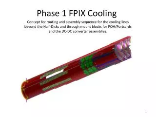
Summary of FPIX tests. Tom Zimmerman Fermilab May 16, 2007. FPIX Block Diagram. DACs used to set biases and reference voltages. Comparators. 1 st stage. 2 nd stage. Pixel input feeds a charge integrator followed by X4 gain stage Gain stage output feeds 8 comparators

Summary of FPIX tests
E N D
Presentation Transcript
Summary of FPIX tests Tom Zimmerman Fermilab May 16, 2007
FPIX Block Diagram DACs used to set biases and reference voltages Comparators 1st stage 2nd stage
Pixel input feeds a charge integrator followed by X4 gain stage • Gain stage output feeds 8 comparators • 8 comparator thresholds, each programmed with a DAC • All DACs referenced to one master bias current (set with external R) • Vref DAC sets DC operating point of 2nd stage • (Vdda) – (operating point of 2nd stage) determines DC bias point of comparators
Option 1: Refres resistor to ground Master current determined only by diode drop voltage level Master current stable, insensitive to Vdda Most bias levels and reference voltages are stable and insensitive to Vdda Comparator bias current quite sensitive to Vdda Option 2: Vmaster resistor to ground Some dependence of master current on parameter variation, Vdda. Most bias levels and reference voltages are mildly dependent on Vdda Comparator bias current much less sensitive to Vdda USE OPTION 2 Master Bias Options
Master bias option 1 With Rbias1 = 585K, vary Vdda: Threshold very stable Comparator bias varies significantly with Vdda
Master bias option 2 With Rbias1 = 1.44Meg, vary Vdda: Comparator bias varies little (desirable!) Threshold varies somewhat (OK)
Biasing for FFR stability • Doing “FFR” reset with previous resistor bias values can result in oscillation (reason for this discussed later) • Select revised Vmaster resistor of 910K (1%) to avoid FFR oscillation (second stage and comparators are completely debiased) • All nominal DAC values must be recomputed and programmed • With 910K bias, Vref and comparator thresholds are about 12 mV/count (this can vary chip to chip) • If FFR cannot be done due to oscillation at power-up (which causes Vddd drop due to current limiting), then: Set Vdda = 0 (which reduces the Vddd supply current), perform FFR, program desired register values, and then restore Vdda.
Gain and calibration issues • Sensor capacitance (pixel input to HV backplane) is consistently 10 fF. • FPIX charge gain is determined by integrator feedback capacitance • Integrator feedback C is made from ILD parasitic: not well controlled! • Large variation in charge gain from chip to chip (I saw anywhere from 290 mV/fC to 500 mV/fC! • Test pulse input C has the same uncertainty • The only way to calibrate a chip’s charge gain is to inject a known charge through the 10 fF sensor capacitance, by applying a known step voltage to the sensor backplane. • Perhaps each chip should be calibrated during test?
Comparator DC bias issues • Very important since it affects stability (discussed later) • Measure the comparator bias current for different Vref DAC settings on one chip. This bias current will affect the comparator delay. • The chip measured has the lowest comparator bias current of all 8 chips on the tested module, for a given Vref setting. I measured a 50% spread in comparator bias currents (for a given Vref) over the 8 chips.
Comparator delay/timewalk • Approx. 12 mV/(DAC count) • Set threshold (Vth0) to 10 counts below Vref • Threshold offset of several counts • Effective threshold is therefore about 1400 e • Chip charge gain is 340 mV/fC • Desired Vref 120 – 125 counts? (Comparator bias ~ 0.8 uA) Input = 1600 e Input = 1800 e
Input = 2000 e Input = 2400 e Input = 3600 e Input = 7200 e
Stability problems • Several positive feedback paths exist • Feedback strength depends on several factors, some under our control and some not
Instability due to DAC leakage current • Thousands of DAC sections driven by master reference • Each section has Ileak due to digital switch • Leakage current into switch depends on (Vdda – Vddd) • If Vdda > Vddd, leakage is big enough to subtract significantly from master reference current, lowering Vref • Lower Vref to the 2nd stage increases the comparator bias current. This reduces on-chip Vdda due to parasitic supply bus resistance, which lowers Vref even more: positive feedback! • Solutions: • always set Vdda = Vddd – 0.2V • Bypass Vref to ground with at least 0.1 uF
AC instability • Feedback paths from comparators back to integrator through common parasitic resistance in both ground and Vdda busses, and capacitance from ground and Vdda to the integrator input • Factors affecting feedback strength: • Comparator gm (depends on comparator bias and # of sections used) • Parasitic R in ground supply bus (shunted somewhat by substrate) • Parasitic R in Vdda supply • Parasitic C from Vdda to integrator input • Sensor C from external ground to integrator input • Integrator feedback C • Substantial chip to chip variation in several of these quantities!! • Unavoidable chip to chip variation in sensitivity to oscillation
“Best” configuration • Vdda = 2.3V, Vddd = 2.5V • Bias with 910K from Vmaster to ground (no Refres resistor) • 0.1 uF or bigger bypass from Vref to ground • 0.1 uF or bigger bypass from Vbp1 to ground • 0.1 uF or bigger bypass from Vth0 to ground (for threshold stability) • Minimize Vdda and ground resistance on HDI • 0.01 uF bypass cap from Vmaster to Vdda (for ESD protection only). Note this cap must be at least a factor of 10 smaller than the Vref bypass to avoid oscillation through the path described by the leakage current problem • Suggested DAC settings (?): Vref=122, Vth0=112, Vfb2=103, Ibp1=0, Ibp2=0, Ibb=18, Iff=8
Stability tests for 8-chip module • As soon as any one chip begins to oscillate, the whole module oscillates • Look at module stability as a function of: • how many of the 8 comparators are enabled • Vref setting • how many chips are enabled
3 comparators on • 8-chip HDI with sensor: measure minimum Vref that avoids oscillation • On this particular module, chip #8 is most sensitive to osc. • When multiple chips are enabled, the min. Vref is several counts higher than the most sensitive individual chip • Safe Vref setting would be well above the min. Vref
8 comparators on 4 comparators on 2 comparators on 1 comparator on
Conclusions Proper biasing, bypassing, etc. can help immunity to oscillation, but by far the 2 most important factors are: -- comparator bias current -- # of comparators used At present, we have tested only one 8-chip module with a sensor. There is significant chip to chip variation in sensitivity to oscillation. The sensitivity of the module as a whole is determined by the weakest chip. With a reasonable comparator bias current, operating one comparator seems safe, but using more than one comparator is not!! Separating the integrator and comparator supply nets should solve this problem, but would require a new run.