Download
1 / 10
100 likes | 258 Vues
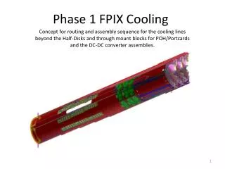
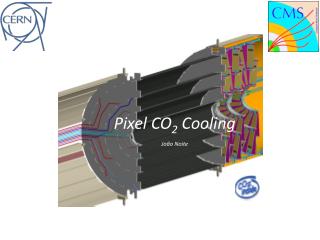
FPix Cooling Circuit. FPix Shared HD - Nominal Flow. Δ P t otal = 5bar Δm = 0.5g/s m nominal = 2.6g/s. Δ P t otal = 10bar Δm = 0.2g/s m nominal = 2.2g/s. FPix HD evaporators in series configuration.

E N D
FPix Shared HD - Nominal Flow ΔPtotal = 5bar Δm = 0.5g/s mnominal = 2.6g/s ΔPtotal = 10bar Δm = 0.2g/s mnominal = 2.2g/s • FPix HD evaporators in series configuration. • Inlet capillaries sized for 10bar show less flow variation when the other parallel HD is switched off. • Flow varies from 2 to 2.4g/s due to heat load differences between parallel loops. • Inlet capillary used has 0.8mm ID and 2m length but can be sized according to the available space. • Based on the results, the total mass flow consumed by FPix is foreseen to be 30g/s.
FPix HD Tube ID 1.3mm Tmax = -12°C Inlet capillary: ID=0.8mm L=1.42m DC-DC Converter + PC Half Disk Boiling trigger Low margin wrt Dryout at maximum power
FPix HD Tube ID 1.4mm (baseline) Tmax = -13.5°C Inlet capillary: ID=0.8mm L=1.75m DC-DC Converter + PC Half Disk Good transition to boiling Ideal 2-Phase flow regime and good margin wrt Dryout
FPix HD Tube ID 1.6mm Tmax = -15.5°C Inlet capillary: ID=0.8mm L=2.08m DC-DC Converter + PC Half Disk Perfect transition Optimum performance and large safety margin
FPix HD at 15°C and Ready for Data Tmax = 17.3°C HD 1.4mm ID Inlet capillary: ID=0.8mm L=1.75m DC-DC Converter + PC Half Disk Small safety margin
BPix Parallel Loops Mockup DAQ System Panels Full -Z Layer #4 Circuit • BPix –Z Layer 4# complete cooling circuit, all 4 parallel loops. • Mockup designed and built to investigate the flow behavior of parallel loops under heat load imbalance conditions. • Development of LabView integration together with MatLab and Refprop to be able to measure individual loop mass flow by using differential pressure across each inlet capillary.
BPix Flow Distribution Mockup Full -Z Layer #4 Circuit assembled at B158 Outlet Manifold Inlet Manifold and Capillary Area BPIX DC-DC and PC PT100 Instrumentation ΩHeating Method
YBO CO2 Transfer Line Sizing Concentric Tube HEX Transfer Line 30m line results into ΔPmax = 0.45bar ≈ 1°C • Assembly example, tube length not to scale • The CO2 transfer line regulates the detector inlet liquid temperature via internal heat exchange with the detector’s returning flow. • Max required mass flow up to 10g/s at main transfer line from manifold to PP0. • 2-Phase pressure drop models indicate a loss of 1°C. • 16m experimental setup is being built at B158 to verify. Pixel Nominal Conditions