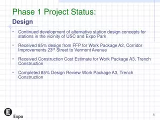
Phase 1 FPIX Module Assembly Status Update at Purdue University for CMS FPIX Mechanical Group
This report details the current status of the Phase 1 FPIX module assembly conducted by the CMS FPIX Mechanical Group at Purdue University. It includes updates on various components such as flex cable strain relief, SMT connectors, and semi-automated assembly processes. Significant advancements have been made in HDI-to-sensor gluing, with promising initial results from stamping epoxy, as well as improvements in gantry controls and LabVIEW programming for pixel module assembly. Additional plans for FPIX module testing and future wirebond encapsulation methods are discussed.

Phase 1 FPIX Module Assembly Status Update at Purdue University for CMS FPIX Mechanical Group
E N D
Presentation Transcript
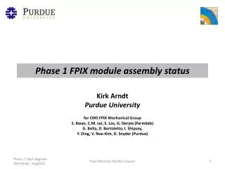
Phase 1 FPIX module assembly status Kirk Arndt Purdue University for CMS FPIX Mechanical Group S. Kwan, C.M. Lei, S. Los, G. Derylo (Fermilab) G. Bolla, D. Bortoletto, I. Shipsey, Y. Ding, V. Noe-Kim, D. Snyder (Purdue) Pixel Modules Parallel Session
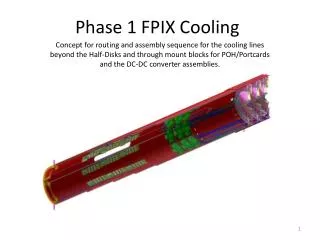
Phase 1 FPIX module Flex cable strain relief (built into module end holder) Flexible Printed Circuit SMT connector (SMK CFP8730-0101F) HDI Flat flex cable 75cm length (short “connector saver” pigtail flex will be used for testing during assembly) Module end holder (with thru hole for #00 or M1.2 screw) TBM 2x8 ROCs FPIX sensor Pixel Modules Parallel Session
Flex cable and strain relief insertion sequence Threaded insert in module end holder (for engagement with screw thru hole in blade) Connector cover flips and locks easily with only a small force to connect flex cable Pixel Modules Parallel Session
Flex cable strain relief trial It works! Pixel Modules Parallel Session
Semi-automated module assembly HDI flex and TBM 2x8 Bump-Bond Module • Status • For HDI-to-sensor gluing, beginning trials using a stamp on the ‘pick-and-place’ machine to improve the uniformity of epoxy dispensing (similar to the process used by BPIX). • Early results on stamping Araldite 2011 epoxy on glass slides look promising… Pixel Modules Parallel Session
Update: module assembly and testing at Purdue/Nebraska • Completed reverse engineering of custom front-end tools on loan from UCSB. Designs sent to Nebraska for machining of the tools for Nebraska and Purdue gantry systems. • Aerotech software upgrades in progress to make Purdue and Nebraska gantry controls identical. • Completed LabVIEW program at Purdue with all functionality required for pixel module assembly as baseline code for commissioning Nebraska system (see video at http://www.youtube.com/watch?v=qMs_w89dnXc) • Plan to adopt the PSI cooling box for FPIX module testing…received drawings and parts list from Andrei Starodumov (…need to follow-up with Philipp Eller for the changes that ETHZ made to the design) • Parts for two boxes will be purchased by Kansas University and machined and assembled at Nebraska…one will go to Purdue. Pixel Modules Parallel Session
Wirebond encapsulationpast and future Pixel Modules Parallel Session
From CMSFPIX Tech Board Meeting – Dec 1, 2006 (full report in backup slides) Vibrations click here for the movie • Vibrations are detected all the way down to 3x8 pixels pulsed in all ROCs that correspond to a current of ~8 mA in the single Bond being investigated. • More pixels implies more current and so larger amplitude. • The frequency detected is ~14 KHz and obviously the wire oscillates also when pulsed at 7Khz and 3.5KHz, but the amplitude goes down Pixel Modules Parallel Session
FPIX Plaquette Encapsulation The encapsulant (Dow Corning Sylgard 186) is removable. Wirebonding can be done again in case of failures The 2-part encapsulant is mixed, poured into a syringe and degassed in a vacuum or centrifuge The syringe is connected to an air powered fluid dispenser and inserted into a holder on a 3-axis stage (motion along rows of bond feet is motor-controlled). Shape of encapsulant beads is determined by the rate of volume dispensed and the rate of motion of the syringe Mixed encapsulant should be used between ~0.5 and ~1.5 hours after mixing. Fixture cure at room temp. is ~8 hours, full cure in 48 hours. Estimate ~3 hours to encapsulate 6 plaquettes (including mixing and clean-up time). See section 3.3 “Wirebonding and encapsulation” in Assembly and qualification procedures of CMS forward pixel detector modules, Nucl. Instrum. Meth. A638, Issue 1, 11 May 2011, Pages 55–62, doi:10.1016/j.nima.2011.02.106 Pixel Modules Parallel Session
FPIX Encapsulation result ROC and VHDI wire bond feet were potted in separate encapsulant beads for each ROC Pixel Modules Parallel Session
Bead dimensions height ~100 um height ~150 um width ROC bead ~600 um width VHDI bead ~900 um Pixel Modules Parallel Session
Phase 1 FPIX encapsulation • Use 3-axis motion-controlled “robot” and programmable dispenser controller for increased accuracy and repeatability • Would be nice to add camera to robot for pattern recognition alignment of dispensing pattern-to-module wirebonds • Will try conical dispensing nozzle (shown above) with 50 micron ID orifice (used 100 micron ID syringe needle in the past) Pixel Modules Parallel Session
flex cable strain relief design Gold plated area 12.8 mm X 2.5 mm, Non-bendable region
Step 1: Place Flex cable in front of connector; Bend at ~5 mm from end. Step 2: Insert Flex cable into connector; Bend at 7.5 mm from end. Step 3: Snap in the cap (handle not shown) Flex cable strain-relieved.
The insertion direction is reversed so that friction locks the plug when the cable is pull accidentally from the free end. • Locking feature = deflection tip at the front end of the plug. • Need experience with prototype.
Having trouble finding a manufacturer of a “textured” stamp similar to the stamp used by BPIX (on the left). • Closest I’ve found is shown on the right.
Purdue status Report • The main topic is encapsulation or not, and if so how G. Bolla, P. Merkel, I. Shipsey, K. Arndt, G. Arndt, D. Graves, D. Bortoletto, C. McKinney, I. Childres and more …. CMSFPIX Tech Board Meeting – Dec 1, 2006
Encapsulation or not • Approach • Understand what is going on with measurements • Can be very time consuming, but fun as well • Make an educated decision • Develop the tools and procedures to get the job done
Magnetic field • How do we get it at Purdue? • Cheap • Handy and easy to use • Safe • Compatible with • installing a Plaquette in the field with the ~right orientation • Watching the bonds with high-mag optic • Close to the DAQ (cosmo based thx Rutgers people) • Investigated various options: • Multiple magnets available in the Phys. Bldg. up to 2 T • Similar to what Atac-et-al used • What a pain • it might trip on anything • Schedule with other users • Not really my style • Make a SHOPPING LIST • Bought some nice permanent magnets ($150 for the whole thing) • Neodymium Iron Boron (NdFeB) Magnets • 2 inches diameter and 2 inches thick (a beauty but I had to spend 2 hours on the phone with the vendor for safety reasons; He thought I could not handle them properly and I was going to be killed by them) • Safety first so Kirk (the wise guy) helped and set up a safe frame for the new toys • Bought some first surface mirror to get the bond image out to the stereoscope • 6$ a piece (I bought 10 of them) • Handy 9mmx9mm I can put them anywhere and they are compatible with a small gap between the magnets 9/SQRT(2)=~6.4 mm between the magnets (~ 0.4 inches for the Yankees) • Coupled our lab digital camera to the stereoscope and take movies and pictures
Mapping the field with a GAUSSmeter Mapping of the B-field. The field is above 0.9 T within a radius of 2 cm. The grid of the map in in 5mm steps. This matches pretty well the predictions done when we made the shopping list.
Frequencies of interest are the ones associated with the beam cycle/s • f(88.924ms) is 11.24 KHz • And many others (higher than….) Current variations (Source: Roland H. at the upgrade workshop) Source: http://sl.web.cern.ch/SL/sli/new_filling.gif Magnitude of the current spikes Per BOND: 8mA/2bonds= 4 mA in a single ROC (inside a Plaquette) From VHDI-to-HDI 8mA*N_ROC/8 (8mA*N_ROC/4) in a 2xN(1xN) Plaquette: 2x5 and 1x5 is 10 mA, 2x4 is 8 mA 2x3 is 6 mA 1x2 is 4 mA Width of the spikes: 3 ms (t5), ~1 ms (t3 and t4), ~0.2-0.3 ms (t1 and t2)
Tektronix TCP202 AC/DC Current Probe Idig versus time • Borrowed a current probe from EE. • Replaced the Vdig connection between the Plaquette and the FANOUT module with a wire (bypass the connector) • This allows for monitoring of the current to the Plaquette with extreme precision in time and about 1mA resolution • The current I measure is the one flowing on the VHDI to HDI (fanout board) bonds. • I cannot find a way to measure directly the current in the ROC bonds
READOUT of 6 ROCs I have chosen to set the ROCs With the wrong WBC in order NOT to have a long, long READOUT • This is hard to get in house • Get smart (Gino You should call for help) Trigger Cal inj
Precision of the method • Clearly capable to detect the <1mA during readout (0.75 mA from the PSI46V2 Manual)
Using the ROC as a pulse tuner • Depending on the pattern and number of pixel you inject you can get different shape pulses on the digital current
Vibrations click here for the movie • Vibrations are detected all the way down to 3x8 pixels pulsed in all ROCs that correspond to a current of ~8 mA in the single Bond being investigated. • More pixels implies more current and so larger amplitude. • The frequency detected is ~14 KHz and obviously the wire oscillates also when pulsed at 7Khz and 3.5KHz, but the amplitude goes down
Remarks • The expected current variation induced by the abort gaps (inactivity) of the LHC on the digital power supply of the ROC are reproducible (Inverted) by injecting charge in multiple pixels in a Plaquette with a good tuning capability • With a 0.9 T magnetic field wirebonds can be seen to oscillate with current pulses as small as 8mA (we cannot exclude that at lower current the wire vibrates with an amplitude lower than our detection threshold) • This translate to <2mA for a 4T field • Should we worry also about the AOUT bonds and maybe some others? • The per BOND current swing expected in LHC are up to 10mA for FPIX • Encapsulation (or something else) is mandatory! • We started a process of learning how to encapsulate the bonds in the plaquettes (next 4 transparencies) • Great help from the expertize and equipment left over by the CLEO detector construction
Encapsulation The encapsulant (Sylgard 186) is removable. Wirebonding can be done again in case of failures. The 2-part encapsulant is mixed, poured into a syringe and degassed in a vacuum. The syringe is connected to an air powered fluid dispenser and inserted into a holder on a 3-axis stage (motion along rows of bond feet is motor-controlled). Shape of the encapsulant bead is determined by the rate of volume dispensed and the rate of motion of the syringe. Mixed encapsulant should be used between ~0.5 and ~1.5 hours after mixing. Fixture cure at room temp. is ~8 hours, full cure in 48 hours. Estimate ~3 hours to encapsulate 6 plaquettes (including mixing and clean-up time).
Encapsulation trial result ROC and VHDI wire bond feet are potted in separate encapsulant beads for each ROC.
Bead dimensions height ~100 um height ~150 um width ROC bead ~600 um width VHDI bead ~900 um
Checking the outcome • Does it still work? YES • Any effect on the Analog OUT (different capacitance due to the different dielectric on the bonds) NO • Yet to be done: • Thermal cycling • I cannot see a problem with it (with the geometry of the BEAD that Kirk achieved). • Will do this w-e • Vibration tests • Will get done after CERN
Conclusions (encapsulation) • As a group we believe there is no question left and the encapsulation is mandatory • We have a way to encapsulate the bonds on plaquettes that is reliable and fast enough • A few crosschecks to be done • If a decision is taken, we will start encapsulating the bonds before the next shipment.