Innovative Cooling Loop Design for Phase 1 FPix Project by Kirk Arndt (2012)
This documentation provides an in-depth analysis of the Phase 1 FPix Cooling Loop Design, focusing on the tubing couplers and thermal performance optimization. The design involves bonding tubing permanently through couplers positioned between rings, aiming to enhance cooling efficiency via careful examination of pressure drop and temperature differential (∆T) impacts. The document outlines detailed calculations, material evaluations, and various testing methods, including thermal tests and cooling simulations, to verify the effectiveness of the system under expected heat loads. The findings aim to optimize the cooling circuit for enhanced heat management in the CMS detector environment.


Innovative Cooling Loop Design for Phase 1 FPix Project by Kirk Arndt (2012)
E N D
Presentation Transcript
Phase 1 FPix Cooling Loop Design Kirk Arndt February 1, 2012 (on behalf ofCM Lei, Erik Voirin, Simon Kwan, Joe Howell)
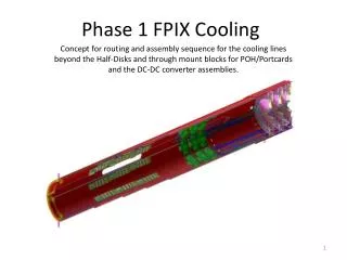
Tubing within Rings Coupler bonded 2 tubing together permanently, further development and proof of feasibility needed Couplers bond tubing between half-rings permanently, further development and proof of feasibility needed HD Tubing Assembly Length = 3,209 mm Typical bending R for tubing beyond ring = 1/8” = 6.35mm CMS Phase 1 FPix Cooling Loop Design
Tubing Length Info Outer Outer Outer Inner Inner Inner Inner Outer CMS Phase 1 FPix Cooling Loop Design
Baseline Design of HD Cooling Tube 1.435mm ID/1.638mm OD SS tubing connects all rings in a Half-Disk in series To optimize: • examine the ∆T reduction vs. material increase if changing to 1.63mm ID tubing. • examine the ∆T reduction vs. material increase if changing to parallel flow to Outer Assembly and Inner Assembly. • conduct a 4-blade thermal test to verify the ∆T from coolant to pixel modules. • conduct a single tube mock-up CO2 cooling test to verify the ∆T along the tube with simulated detector heat load. CMS Phase 1 FPix Cooling Loop Design
Cooling Calculations for HD1 << Courtesy from Joao Noite >> Ring I-O of the 4 rings is cooled last Tubing diameters and lengths are the same from point 1 to point 6 before coolant entering O-O, and on the return line from point 10 to point 11. CMS Phase 1 FPix Cooling Loop Design
HD1 (1.435mm ID) HD1 (1.63mm ID) ST Supply ST Supply DC-DC DC-DC ST ST PC PC ST ST O-O O-O O-I O-I I-I I-I I-O I-O ST Return ST Return liquid starts boiling at ~-17°C corresponding to saturation pressure of 22.1 bar liquid starts boiling at ~-18°C corresponding to saturation pressure of 21.2 bar CMS Phase 1 FPix Cooling Loop Design
HD1 (1.435mm ID) HD1 (1.63mm ID) B B B B M M M M D D D D A A A A O-O O-O O-I O-I I I I I SLG SLG SLG SLG SW SW SW SW S S S S CMS Phase 1 FPix Cooling Loop Design
HD1 (1.435mm ID) HD1 (1.63mm ID) B B B B M M M M D D D D A A A A I I I I SLG SLG SLG SLG SW SW SW SW S S S S I-I I-I I-O I-O CMS Phase 1 FPix Cooling Loop Design
HD1 (2.0-1.43-2.8mm ID) HD1 (2.0-1.63-2.8mm ID) Conclusion: Larger tubing performs better with extra 6% margin from dryout. CMS Phase 1 FPix Cooling Loop Design
Baseline Serial Flow Layout Possible Parallel Flow Layout 3 removable couplings; each weighs 0.7 g 2 permanent couplings btw outer & inner rings 1 supply + 1 return tube per HD 4 removable couplings 2 permanent couplings btw outer & inner rings 2 supply + 2 return tubes per HD CMS Phase 1 FPix Cooling Loop Design
Possible Parallel Flow Layout Want to calculate ∆P & ∆T of parallel flow to Outer and Inner Assemblies with 1.435mm ID tubing in rings CMS Phase 1 FPix Cooling Loop Design
Study on whether the Inner-Inner ring should be cooling last << The total ∆T across the 4 rings is the same >> HD1 (2.0-1.43-2.8mm ID) -16.9oC -17.6oC -18.2oC -19.2oC Existing I-I start if cooling second-to-last These temperatures were used as the heat sink temperatures for the blade FEA (see next slides) These temperatures were used as the heat sink temperatures for the blade FEA New I-I start if cooling last CMS Phase 1 FPix Cooling Loop Design
Comparing results with different heat sink temps TIM conductivity at blade ends = 1 W/m-K Baseline, Inner Outer Ring cooled last: Inner Outer ring temp = -17.6oC Inner Inner ring temp = -16.9oC Max Temp on Module = -11.1oC ∆T = 6.5 C across the whole model Alternative, Inner Inner Ring cooled last: Inner Outer ring temp = -16.9oC Inner Inner ring temp = -18.2oC Max Temp on Module = -11.3oC ∆T = 6.9 C across the whole model CMS Phase 1 FPix Cooling Loop Design
Comparing results with different heat sink temps TIM conductivity at blade ends = 34 W/m-K Module inner radius end temp = -15.5oC Module inner radius end temp = -16.5oC Alternative, Inner Inner Ring cooling last: Inner Outer ring temp = -16.9oC Inner Inner ring temp = -18.2oC Max Temp on Module = -15.1oC ∆T = 3.1 C across the whole model Baseline, Inner Outer Ring cooled last: Inner Outer ring temp = -17.6oC Inner Inner ring temp = -16.9oC Max Temp on Module = -14.9oC ∆T = 2.7 C across the whole model CMS Phase 1 FPix Cooling Loop Design
Summary on FEA Results on Which Ring is Cooled Last Inner-Outer Ring cooled last (existing design) in the 4-tubing series connection scheme has a smaller ∆T, but at a slightly warmer module temperature. CMS Phase 1 FPix Cooling Loop Design
Backup slides CMS Phase 1 FPix Cooling Loop Design
4-Blade Thermal Testing Assembly 2 blades will be bonded to C-C ring segments with indium and the other 2 with thermally conductive epoxy Coating process on parts is being prepared Tooling for bonding blades was machined (this was designed for epoxy joints, some adjustments are needed for bonding with indium due to thermal changes) Some dummy 2x8 modules with module holders and flex heater were made Considering indium as the thermal filler between the tubing and the ring groove CMS Phase 1 FPix Cooling Loop Design
Study on Heat Transfer of Different Tubing Sizes in C-C Ring Groove Temp Plot on Epoxy Only These FEA results appear overly optimistic…considering indium as the thermal filler between tubing and ring groove to promote heat transfer into the tube CMS Phase 1 FPix Cooling Loop Design
A New Plastic Prototype for the HD Outer Assembly - will be used to check fit of tubing with bends and coupling fittings CMS Phase 1 FPix Cooling Loop Design
CO2 Cooling Coupling Design Female nut with M3.5 threads Gland welded with tubing Replaceable aluminum gasket Male nut with M3.5 threads and welded with tubing Front face with knife-edge Front face with knife-edge CMS Phase 1 FPix Cooling Loop Design
CO2 Cooling Coupling Status • Two sets of assemblies were laser-welded • Direct welding was done on gland • Welding rod 312 SS was used for male thread nut because of larger part tolerance (0.005” vs. 0.002”) • Vacuum leak check was made on both assemblies • No leak on aluminum washer sealing • No leak on gland weld • Leak on the male thread nut weld • Quick conclusion: Design and fabrication method OK, but requires tighter fitting tolerance • Plan: leak on the weldment will be fixed and a pressure test will be conducted before a new round of coupling parts is machined. • Will follow Hans suggestion and try vacuum brazing or low-temp soldering (which would remove the need for threaded couplers) Weld for gland Weld for male threaded fitting CMS Phase 1 FPix Cooling Loop Design