Download
1 / 31
310 likes | 489 Vues
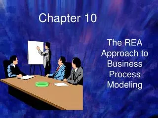
The Traditional Approach to Requirements: Using Dataflow Diagrams. Spring 2014. Traditional versus Object-Oriented Approaches. Traditional Approach -Requirements Models. Data Flow Diagrams (DFDs). Graphical system model that shows all main requirements for an IS in one diagram

E N D
The Traditional Approach to Requirements: Using Dataflow Diagrams Spring 2014
Data Flow Diagrams (DFDs) • Graphical system model that shows all main requirements for an IS in one diagram • Inputs/outputs • Processes • Data storage • Easy to read and understand with minimal training
Advantages of the Data Flow Approach • Freedom from committing to the technical implementation too early • Understanding of the interrelatedness of systems and subsystems • Communicating current system knowledge to users • Analysis of the proposed system
Basic Symbols • A double square for an external entity • An arrow for movement of data from one point to another • A rectangle with rounded corners for the occurrence of a transforming process • An open-ended rectangle for a data store
The Four Basic Symbols Used in Data Flow Diagrams, Their Meanings, and Examples (Figure 7.1)
External Entities • Represent another department, a business, a person, or a machine • A source or destination of data, outside the boundaries of the system • Should be named with a noun
Data Flow • Shows movement of data from one point to another • Described with a noun • Arrowhead indicates the flow direction • Represents data about a person, place, or thing
Process • Denotes a change in or transformation of data • Represents work being performed in the system • Naming convention: • Assign the name of the whole system when naming a high-level process. • To name a major subsystem attach the word subsystem to the name. • Use the form verb-adjective-noun for detailed processes.
Data Store • A depository for data that allows examination, addition, and retrieval of data • Named with a noun, describing the data • Data stores are usually given a unique reference number, such as D1, D2, D3 • Represents a: • Database • Computerized file • Filing cabinet
Creating the Context Diagram • The highest level in a data flow diagram • Contains only one process, representing the entire system • The process is given the number 0 • All external entities, as well as major data flows are shown
Basic Rules • The data flow diagram must have one process. • Must not be any freestanding objects • A process must have both an input and output data flow. • A data store must be connected to at least one process. • External entities should not be connected to one another.
Drawing Diagram 0 • The explosion of the context diagram. • May include up to nine processes. • Each process is numbered. • Major data stores and all external entities are included.
Drawing Diagram 0 (Continued) • Start with the data flow from an entity on the input side. • Work backwards from an output data flow. • Examine the data flow to or from a data store. • Analyze a well-defined process. • Take note of any fuzzy areas.
Data Flow Diagram Levels • Data flow diagrams are built in layers. • The top level is the context level. • Each process may explode to a lower level. • The lower level diagram number is the same as the parent process number. • Processes that do not create a child diagram are called primitive.
Creating Child Diagrams • Each process on diagram 0 may be exploded to create a child diagram. • A child diagram cannot produce output or receive input that the parent process does not also produce or receive. • The child process is given the same number as the parent process. • Process 3 would explode to Diagram 3.
Creating Child Diagrams (Continued) • Entities are usually not shown on the child diagrams below Diagram 0. • If the parent process has data flow connecting to a data store, the child diagram may include the data store as well. • When a process is not exploded, it is called a primitive process.
Differences between the Parent Diagram (above) and the Child Diagram (below) (Figure 7.4)
Checking the Diagrams for Errors (Figure 7.5) • Forgetting to include a data flow or pointing an arrow in the wrong direction
Checking the Diagrams for Errors (Continued Figure 7.5) • Connecting data stores and external entities directly to each other
Checking the Diagrams for Errors (Continued) • Incorrectly labeling processes or data flow • Including more than nine processes on a data flow diagram
Checking the Diagrams for Errors (Continued) • Omitting data flow • Creating unbalanced decomposition (or explosion) in child diagrams
Typical Errors that Can Occur in a Data Flow Diagram (Payroll Example) (Figure 7.5)
Ref • Systems Analysis and Design, Kendall & Kendall, 2014 • Object-Oriented Systems Analysis and Design Using UML by Bennett, McRobb, Farmer, 2013