Chapter 7: Analyzing Systems Using Entity Relationship Diagrams
Chapter 7: Analyzing Systems Using Entity Relationship Diagrams. Instructor: Paul K Chen. Analyzing Systems Using Entity Relationship Diagrams. Data Model: What, Why, When? Pre-modeling Activities Conceptual Data Modeling: What, Why, When, Who? Data Modeling Approach

Chapter 7: Analyzing Systems Using Entity Relationship Diagrams
E N D
Presentation Transcript
Chapter 7: Analyzing Systems Using Entity Relationship Diagrams Instructor: Paul K Chen
Analyzing Systems Using Entity Relationship Diagrams • Data Model: What, Why, When? • Pre-modeling Activities • Conceptual Data Modeling: What, Why, When, Who? • Data Modeling Approach • Logical Data Modeling: What, Why, When, Who? • Data Warehousing Data Modeling
What’s a Data Model? A data model is a collection of constructs, business rules and sample data which together supports a dynamic representation of real world objects and events. • Constructs: entity-relationship diagrams (conceptual & logical or functional) and tables (tables) • Business rules: constraints such as referential integrity rules and operators (add, update, delete) • Sample Data for verification and prototyping: Verifying the accuracy of the model.
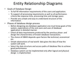
Objectives • Testing the real system before building it. • Assisting in understanding data requirements. • Facilitating physical data base design.
Types of Models • Conceptual Data Model • Logical Data Model • Physical Data Model
Pre-modeling Activities • Modeling format (JAD session or something else) • Roles and responsibilities • Tools and repository • Naming standards • Modeling convention (What methods to use) • Data protection/Backup and recovery procedures
Conceptual Data Modeling: What, Why, When, Who? What is it? • It is a conceptual representation of data without concern for its logical (functional) or physical aspects. • It is a set of high-level business data models which provides a framework for the data modeling activities at the next level.
Conceptual Data Modeling: What, Why, When, Who? When should it be done? • In support of the data requirements of a process model under development at the corresponding level. or 2. Outside the system application lifecycle on a department, division, or company wide basis.
Conceptual Data Modeling: What, Why, When, Who? Who should do it? • The group responsible for assuring that data structure reflects business policies and rules. 2. It should be a joint effort between the owners and custodians of the data, the users of the data, and the analysts.
Conceptual Data Modeling: Why? • Documents the type of data (information) which must be represented in a system independent of specific application, organizations, or technology. • Maximizes data sharing; minimizing redundancy. • Provides foundations for physical database design. • Describes the unique business enterprise specifically
Conceptual Data Modeling: Why? • Outside of application life cycle on a company-wide basis. • Data modeling expresses inherent associations which are the most part, independent of anyone one application. • Data entities change very little even through the way they are used can change for each application. • A complete maintained conceptual data model should shorten the requirements definition phases of system development life cycle.
Data Modeling: Approach • Data partitioning Use a top-down approach to define the data requirements of a system. The purpose is to divide and conquer (from subject to entity), and to evolve from the conceptual level to logical level until physical database is derived. • Standard deliverables For each of the levels, there is a set of standard deliverables that must be produced. The documentation items must be well defined so that the data at each level is well understood.
Data Partitioning (How) (What, Why, Who, Where) Subjects Conceptual Level Technical considerations Entities (Data access/performance Data integrity/recovery) Relationships Logical Level Data Elements Frequencies Data Definition Language -DDL(create, Alter, drop tables) Data Manipulation Language (select, insert, delete, update)
Data Partitioning 1. Define the system boundary – Data Context Diagram. 2. Partition a subject into entities. 3. Discover entities -super-type and subtype; part and whole. 4. Define associations between entities. 5. Define major attributes. 6. Define unique identifier for the entity. 7. Assign cardinalities and set up relationships between the entities. 8. Define integrity rules and apply normalization rules. 9. Validate the model. 10. Complete and standardize the data elements.
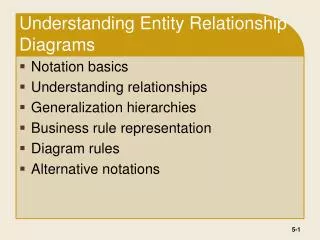
Understand terms and Terminology • Independent entity (fundamental entity) • Dependent entity (Attribute entity) • Associative Entity • Identifying relationship • Non-identifying relationship
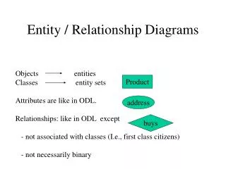
Understand terms and Terminology • Identifier An attribute distinctly identifies each occurrence of an entity. For ex., bank account Id. , and student Id. • Association (relationships) An association is a relationship between two or more entities. Employee works for company Part has item
Understand terms and Terminology • Cardinality(the form of relationship) Associations occur in there forms: one-to-one; one-to-many; many-to-many • Tables A table is a two-dimensional representation of data consisting of columns and rows. • Primary Key Used to identify entities. Unique identification for a row in a table. Allow no nulls and no duplicates. May be system assigned.
Understand terms and Terminology • Foreign key A foreign key is one or more data elements whose value is based on the primary identifier of another entity, thus allowing the system to ‘join’ and get related information from other entities. The ‘joining’ of different entities in this manner eliminates the need of data repetition and redundancy. • Normalization A technique to make sure that the data in a logical model is defined once and only once. Normalization helps minimum data redundancy, and minimize update abnormalities.
1. Define the System Boundary by Subject Context Diagram • A subject (a group of entities with strong affinity) is a class of data objects representing the mission and resources of the organization. • “Subjects” provides mechanisms for controlling how much of a model a reader (user, analyst, manager) is able to consider and comprehend at a time. For a small system, go directly to define entities. For ex: Library (subject) decomposed into book, member, and account. (entities).
ATM ERD –Subject Context Level Customer ATM uses Has Owns Bank Consortium Account Affiliated Bank Holds Consists of
Data (Subject) Context Diagram • A Data context diagram is a special case of ERD in which a single diagram represents the problem domain in terms of data requirements. For example: The ATM diagram illustrates and highlights Several important characteristics of the system: • The people and organization with which the system communicates. • It documents the significant connections (relationships) between the data objects within as well as outside the problem domain.
2. Partition a Subject into Entities Criteria for partitioning a subject into entities are: • The entities included in a subject all tend to describe the subject and have a strong affinity with the subject. • The entities of a subject should be of equal importance, as measured by the range, complexities or importance of their data. • Each entity should belong to only one subject.
3. Discover Entities To find potential entities (entities are nouns), look for: • Objects can be generalized or specialized • The entities of a subject should be of equal importance, as measured by the range, complexities or importance of their data. • Each entity should belong to only one subject
Subtype and Super-type Faculty Full Time Faculty Part Time Faculty Part (day) Time Faculty Part (Night)Time Faculty
Generalization & Specialization Aircraft Specialization Generalization Commercial Military 747 777 B52 B-1B
4. Define AssociationsBetween Entities Use a verb to describe associations between two or more entities that the user wants to keep track of. Each relationship must be specific as possible so that its meaning is clear. An individual owns a building. Owns: possession, rental; or management?
5. Define Major Attributes All the attributes of an entity must have meaning for each and every one of the occurrence of the entity. Only elementary data are included in the model. Attributes resulting from process algorithms should not be included in the model. For ex. Entity ‘individual’ has attributes such as name, address; sex (male or female); no. of dependents, etc. But Derived attributes (such as percentage) are not attributes.
6. Define Unique Identifier for the Entity This is an attribute that unambiguously identifies each occurrence of each entity. Some entities do no have their own identifier. These entities are qualified as dependent or week entities. The identifier of the entity to which the dependent entities are associated with must be used to uniquely identify their occurrences. For ex., a ‘child’ entity must have his or her parent identifier to be uniquely identified.
7. Assigning Cardinalities & Setting Up Relationships Between the Entities Cardinality is the minimum and maximum number of times an occurrence of an entity occurs in relationship to another entity. The minimum number: 0 or 1 The maximum number: 1 or M There are three types of associations: One-to-one; one-to-many; many to many.
Continued The relationships could be either as binary, recursive, or ternary. Doctor Patient Binary Part Order Ternary Part/Order Recursive Organization
Recursive Association A recursive association is one in which there is a relationship between An entity and itself. Information Dev Accounting Engineering Payable Product Receivable Facility Nuclear Coal
Continued A many-to-many relationships will result in the creation of a new entity. Order Order # Part Part # 1:M 1:M Part/Order Part #/Order #
8. Define Integrity Rules and Apply Normalization Rules Integrity rules for entities indicate the context in which an entity occurrence may be created, modified, or deleted. They also ensure that the entity is consistent with other entities. For example, a Client (entity) holds an Account (entity). A client cannot be deleted if at least one of his accounts has a balance greater than 0.
Defining Integrity Rules Integrity rules for relationships indicate in which context the relationship is meaningful. They also ensure that it is consistent with other relationships. This is accomplished by placing referential attribute in appropriate entity on the model.
Formalizing a One-to-one Relationship with Referential Attribute Husband Wife *Husband name Other attributes *Wife name Other attributes Husband name Married to Referential Attribute
Formalizing a One-to-Many Relationship with Referential Attribute Dog Dog Owner (1:M) (1:1) * Dog Id Other attributes Dog Owner Id * Dog Owner Dog Owner Id Other attributes Referential Attribute
Formalizing a Many-to-Many Relationship with Referential Attribute Part Order *Part Id Other attributes *Order No Other attributes An associative entity may Participate in relationship With other entity. Order/Part *Order No *Part Id Other attributes Referential Attributes
Referential Integrity Three options: • Restrict: A primary key can not be deleted if there are any dependent foreign key rows. • Cascade: Deleting a primary key row causes the deletion of all dependent foreign key rows. • Set Null: Deleting a primary key row causes all dependent foreign keys values to be set null.
Apply Normalization Rules A technique to make sure the data in a logical data models is defined once and only once. Normalization helps minimum data redundancy, and minimize update abnormalities.Three forms: • First Normal Form • Second Normal Form • Third Normal Form
Normalization • First Normal Form: Relationships between primary key and each attribute must be one-to-one; ie., remove repeating group. • Second Normal Form: All non-key elements are dependent upon the entire primary key rather than any part thereof. • Third Normal Form: Elimination of the dependence of non-key field upon any other field excepts the primary keys.
First Normal Form Item Qty-Store-2 Qty-Store-3 Qty-Store-1 Item No PK 3000 4000 5000 101 The above is an violation of first normal form because there exists a repeated group.
Rule Number 1 • For each occurrence of an entity, there is only one and only one value for each its attributes. Attributes with repeating values form at least one new entity. • N other words, relationship between primary key and each attribute must be one-to-one.
Possible Solution Store Store/Item Store ID Store ID Item- No Qty Sold + PK PK FK FK S1 S1 3000 101 S2 S2 102 4000
Second Normal Form Student/Course Course Name Course No Student No Teacher code Grade Student Name PK + FK FK FK 3.0 Math ST01 100 T2 Lee ST02 4.0 T1 CS Doe 200 Both course name and student name should be removed because They are not related to the entire student/course primary key.
Possible Solution Course Student No Course Name Student Name Student Course No Student/Course
Rule Number 2 • Each attribute must be related to the entire primary key.
Second Normal Process Order Part Part Name Order No Pt-price PartNo Order-Dt PK PK 1/2/01 Nut 1 1 1.5 1/3/01 5 Bolts 2.0 3 Order/Part Order No Partno QTY How about Putting PartName In Order/part Table? PK + 1 123 1 1 5 3 123
Third Normal Form COURSE Course Id Teacher Code Course Name Dept Name Teacher Name Dept -Id PK T1 DOE MH400 Math Math A1 CS DB CS401 T2 CS Lee The relationship between any two non-primary key components must not be one-to-one. What’s wrong with the above?
Rule Number 3 • The relationship between any two non-primary key components must not be one-t-one; ie., remove tables within tables.
The Normal Process Order Customer Cust-Name Order ID Order DT Cust-Id Cust-Id PK PK FK 1 Lee 1 1/2/ 01 1 Sato 1/5/21 3 3 5 It would be a violation of third normal form to place cust-name in the order table.