Evolution of Rotary Cutting Instruments in Dentistry: Design, Mechanisms, and Safety
891 likes | 1.76k Vues
The history of rotary cutting instruments in dentistry reflects significant technological advancements. From the use of hand-rotated chisels in 1728 to the emergence of electric and air-driven handpieces, speed variations have evolved from 300 RPM to over 200,000 RPM. Instrument design, including the essential components of dental burs and their cutting mechanisms, plays a critical role in dental procedures. Understanding the hazards associated with these instruments, including vibration and heat generation, is vital for safe and effective dental practices.

Evolution of Rotary Cutting Instruments in Dentistry: Design, Mechanisms, and Safety
E N D
Presentation Transcript
Historical development. • Rotary speed ranges. • Instrument design. • General Design of Dental Burs & associated terminology. • Dental Abrasive Stone. • Cutting mechanisms. • Hazards with rotary cutting instruments.
Historical development • cutting - thick, bulky chisels and excavators . • The chisel was used to gain entrance through the carious dentin and make its removal possible by hand excavators .
1728 – HAND ROTATED INSTRUMENT. Taft described them as "bur drills".
1728 Hand-rotated 300 instruments • 1871 Foot engine 700 • 1874 Electric engine 1000 • 1914 Dental unit 5000 • 1942 Diamond cutting 5000 instruments • 1946 Old units converted to 10,000 increase speed
GEAR DRIVEN HANDPIECE • Rotary power is tansferred to the straight handpiece by a belt that runs from electric engine over a series of pulleys & a 3 piece extension cord arm. • Function best at low speed because of so many moving parts with metal to metal contact.
Water Driven Handpiece • 1955 • Turbo-jet • Designed as compact mobile unit & only electricity is needed to operate it.
A soundproof cabinet contain a motor, water pump , water reservoir & plumbing for circulating the water. • Water is conveyed to & from the handpiece by a co-axial type tubing.
Belt Driven Handpieces • 1955. • PageChayes • All gears were eliminated by having a small belt run inside the handpiece sheath over ball bearing pulleys in the angle sections. • Improved models -Page-Chayes 909 and the Twin 909
Air Driven Handpieces • 1957 • A small compact unit consists of a handpiece, control box, foot control and various connector hoses. • When the foot control is activated, compressed air flows through the control box and is carried by a flexible hose to the back of the handpiece.
From here the air is directed to the head of the handpiece and is blown against the blades of a small turbine to produce rotation while the greater, part is exhausted at the back of the handpiece or returned to the control box.
The electric motor high-speed handpiece performed as well as, but not better than, the air turbine high-speed handpiece in the fabrication of high-quality cavity preparations . (J Am Dent Assoc,2005, Vol 136, No 8, 1101-1105 )
ROTARY SPEED RANGES Acc. to Charbonneau:- • Conventional of low speed Below 10,000 rpm • Increased or high speed 10,000 to 150,000 Rpm (maximum range of bell- Drivenequipment) • Ultra speed Above 150, 00 rpm
According to Sturtevant • low or slow speeds (below 12000 rpm) • medium or intermediate speeds (12,000 to 200000 rpm) • high or ultrahigh speeds (above 200000 rpm).
Acc. to Marzuonk • a. Ultra-low speed (300-3000 RPM) • b. Low speed (3000-6000 RPM) • c. Medium high speed (20,000-45,000 RPM) • d. High speed (45,000 - 100,000 RPM) • e. Ultra-high speed (10,000 RPM and more
Pressure (P) It has been observed clinically • low speed requires 2-5 pounds force, • high speed requires less force (1 pound) • ultra-high speed still less force (1-4 ounces) for efficient cutting.
Heat production Heat is directly proportional to • 1. Pressure • 2. RPM • 3. Area of tooth in contact with the tool
Vibration • Vibration is not only a major annoying factor for the patient, but it also cause fatigue for the operator . • Vibration is a product of the equipment used and the speed of rotation.
The following criteria should be used in evaluating handpieces : • Friction: Friction will occur in the moving parts of handpiece; especially the turbine. handpieces are equipped with bearings: ball bearing, needle bearings, glass and resin bearings, etc
b. Torque • Torque is the ability of the handpiece to withstand lateral pressure on the revolving tool without decreasing its speed or reducing its cutting efficiency. • Torque is dependent upon the type of bearing used and the amount of energy supplied to the handpiece.
C. Vibration • While some vibration is unavoidable, care should be taken not to introduce it unnecessarily. • Excessive wear of the turbine bearings, will cause eccentric running which creates substantial vibration .
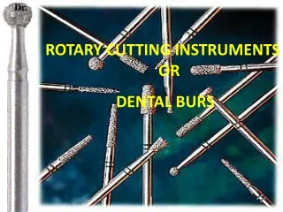
DENTAL BURS • All rotary cutting instruments that have-bladed cutting heads. This includes instruments intended for such purposes as finishing metal restorations and surgical removal of bone, & tooth preparation.
COMMON DESIGN CHARACTERISTICS • three parts: (1) shank, (2) neck, and (3) head.
Shank Design • part that fits into the handpiece, accepts the rotary motion from the hand-piece, and provides a bearing surface to control the alignment and concentricity of the instruments . • straight handpiece shank, • latch-type angle handpiece shank, • friction-grip angle handpiece shank,
Neck Design • intermediate portion of an instrument that connects the head to the shank. • The main function of the neck is to transmit rotational and translational forces to the head.
Head Design • working part of the instrument . • the cutting edges or points that perform the desired shaping of tooth structure. • bladed instruments • abrasive instruments
Historical Development of Dental Burs earliest burs : • expensive • variable in dimension and performance • first machine made burs introduced in 1891
Carbide burs • introduced in 1947 . • All carbide burs have heads of cemented carbide in which microscopic carbide particles, usually tungsten carbide, are held together in a matrix of cobalt or nickel.
In most burs, the carbide head is attached to a steel shank and neck by welding or brazing. • Although most carbide burs have the joint located in the posterior part of the head, others are sold that have the joint located within the shank and therefore have carbide necks us well as heads .
Bur Classification Systems BASED ON MODE OF ATTACTMENT TO HANDPIECE: • latch-type • friction-grip
COMPOSITION: • Stainless steel • Tungsten carbide burs • combination
MOTION: • Right bur • Left bur
LENGTH OF THEIR HEAD: • Long • Short • regular
USES: • Cutting burs • Finishing & polishing burs
1.Head shapes • round, • inverted cone, • pear, • straight fissure, • tapered fissure , • Wheel shaped, • End cutting bur
Round bur • spherical . • initial entry into the tooth , • extension of the preparation, • preparation of retention features/and caries removal. • numbered from ¼, ½, 1, and 2 to 10 .
Inverted cone bur • providing undercuts in tooth preparations . • numbered from 33¼, 33½, 34, 35 to 39.
Pear-shaped bur • A normal-length pear bur (length slightly greater than the width) is advocated for use in Class I tooth preparations for gold foil . • long-length pear bur (length three times the width) is advocated for tooth preparations for amalgam. • They are numbered from 229 to 333 and mainly used in pedodontics.
Straight fissure bur • Elongated cylinder. • amalgam tooth preparation. • They are numbered from 555, 556 to 560 .
Tapered fissure bur • slightly tapered cone with the small end of the cone directed away from the bur shank. • Tooth preparations for indirect restorations. • They are numbered from 168, 169 to 172.
Wheel burs • They are numbered as 14 and 15. • They are wheel shape and are used to place grooves and for gross removal of tooth structure.
End cutting burs • They are cylindrical in shape, with just the end carrying blades. • They are very efficient in extending preparations without axial reduction. • They are numbered from 900 to 904.
Modifications in Bur Design • Reduced use of crosscut , • extended heads on fissure burs , • rounding of sharp tip angles.
General design of dental bur • The dental burs are small milling (cutting) instruments .