Download
1 / 31
310 likes | 419 Vues
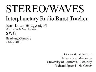
STEREO/WAVES Interplanetary Radio Burst Tracker Jean-Louis Bougeret, PI Observatoire de Paris - Meudon SWG Hamburg, Germany 2 May 2005. Observatoire de Paris University of Minnesota University of California - Berkeley Goddard Space Flight Center. Science Summary.

E N D
STEREO/WAVES Interplanetary Radio Burst Tracker Jean-Louis Bougeret, PI Observatoire de Paris - Meudon SWG Hamburg, Germany 2 May 2005 Observatoire de Paris University of Minnesota University of California - Berkeley Goddard Space Flight Center
Science Summary The STEREO/WAVES (S/WAVES) experiment will: Track and probe CME-driven shocks from the corona to 1 AU Map the in situ structure of CME-driven shocks and flare electron beams Probe the density and IMF structure of the heliosphere before and after CMEs Understand the radio emission process and beam pattern of radio bursts Measure electron density and temperature of filament material in clouds A remote sensing instrument and an in-situ instrument in one Receivers in frequency domain and time domain Sensitive receivers - require an electromagnetically clean spacecraft!
Radio emissions from the inner heliosphere • Radio traces energetic electrons • propagating along magnetic field lines (type III) • accelerated at shock fronts (type II) • trapped in magnetic traps (type I, type IV)
Radio emissions from the inner heliosphere • Radio frequency is determined by the local electron density Ne at the source location • "plasma radiation" on local fp = 9 Ne1/2 or 2 fp • essentially long wavelength radio astronomy l > 10 m ; f < 30 MHz (angular resol. = l /D) • relation observing frequency - distance from Sun
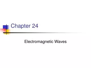
e- 100 R frequency distance 10 R WIND / WAVES time 2 R Type III radio burst (adapted from Marcus Aschwanden)
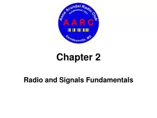
e- 100 R F H 10 R e- WIND / WAVES time 2 R Type II radio burst B transient shock front
SOHO / LASCO WIND / WAVES (after Gopalswamy et al., 2001)
a range of diagnostics obtained with the same instrument and well discriminated on the dynamic spectrum
Radio emissions from the inner heliosphere direction finding • presently (one spacecraft): radio yields full direction + frequency-distance ranging full 3-D localization in space with one instrument BUT - only position of source centroid and equivalent width - need to use average or assumed density model • STEREO major step : - will allow us to refine the density model, - will give us access to propagation effects (IPS-like), - will provide new information on radiation mechanisms, source structure, etc
S/WAVES Measurements Frequency Domain - 2.5kHz to 16MHz Low Frequency Receiver (LFR) 1 channel, 3 bands (160kHz-40kHz), (40kHz-10kHz), (10kHz-2.5kHz) 1 channel, 2 bands (160kHz-40kHz), (40kHz-10kHz) High Frequency Receiver (HFR) 2 channels, 125kHz to 16.025MHz in 319 steps of 50kHz (picket fence) Fixed Frequency Receiver (FFR) 1 channel, 30MHz or 32MHz Time Domain - 30mHz to 125kHz Time Domain Sampler (TDS) has 4 wideband burst channels Snapshots sampled at up to 250,000 samples/second/channel 16Mbits/second acquired (24by7), much less sent to the ground Interval Max - 4 channels LWS histogram Low rate science (64S/s) Sensors 3 orthogonal electric antennas S/WAVES package is identical on both spacecraft
Radio stereoscopy For radio waves, "STEREO" means a lot more than triangulation or 3-D, but triangulation remains a basic need A B
Radio stereoscopy : Parameters and methods • basic physical parameters : • Detailed radiation pattern • 3-D localization of radio sources + propagating effects • group delays • measured parameters: • radio intensity ----> directivity • polarization ----> directivity of modes, propagation • time-of-flight ----> localization, group delays • dynamic spectrum ----> radiation mecanism / propagation • source direction ----> triangulation, propagation • source diameter ----> source structure, propagation • methods : • dispersive diagrams of intensities • statistical analyses as a function of the stereo angle • triangulation • Study of time-of-flights • Correlation studies (in situ plasma, coronagraphs, imagers, ground data)
Radio stereoscopy • Results have been sometimes surprising : • strong directivity (beaming ≈ 15° at HF, 50° at LF) • Non radial orientation of the beam patterns • Evaluation of time-of-flight and group delays (often 'anomalous') • Radio bursts seen behind the Sun (quasi-isotropic halo at low level) • Very rich diagnostic with many tools
What can we learn from radio stereoscopy? • radio radiation mechanisms (S/WAVES / IMPACT) • radiation modes (fundamental and/or harmonic : ambiguity is raised) • Wave-particle correlations (micro-physics) • constraints on theories • local structure and topology of the source • type III bursts (energetic electrons) (S/WAVES / IMPACT / SECCHI) • Radiation mechanism, association with electron events • structure and topology of large scale magnetic fields (mapping) • understanding propagation phenomena (weak/strong scattering) • type II bursts (shock waves) (S/WAVES / IMPACT / SECCHI) • association with Coronal Mass Ejections (3-D localization of the source) • formation and evolution of the shock (study of multiple sources) • acceleration of energetic particules from the shock • interplanetary type III storms (long lasting electr. streams) (S/WAVES/SECCHI) • association with Active Regions and Heliospheric Current Sheet (study in 3-D) • relaxation of magnetic energy in active regions associated with CMEs
U. Calif. Obs. Paris U. Minn. U. Minnesota The S/WAVES instrument
S/WAVES hardware • Main electronics package • Meudon • High Frequency Receiver (FFR, HFR, LFR) • Digital Signal Processor • Minnesota • Time Domain Sampler • Data Processing Unit (HK, LRS, FFR) • Power Supply • Antenna Assembly • Berkeley • Antenna deployment units • Antenna mounting plate • Meudon • Preamplifier electronics • Minnesota • Preamplifier enclosure • Deployment filters • Ground Support Equipment • Minnesota • Data acquisition/access/analysis hardware and software • Test, analysis and display software • Meudon • Stimuli hardware • Test, analysis and display software • Berkeley • RF test caps
Resources • All resources are probably in acceptable shape • Mass 13.23kg against 14.1kg delivery NTE • Power 15.4W against 14.0W delivery NTE - 1.4W • Bit rate 1,916b/s against 2,037b/s minimum allocation • Schedule no slack - APL is waiting • Dollars Program is fully funded, slightly under budget • Euros French program is fully funded • Power has crept up • A request for a power increase is in process - no problem • Current value has been reported to our S/C partners at APL
Insides TDS I/O CPU Analog bay Power supply Antenna filter
And more DSP Preamp HFR
SWAVES Current Status • Both receivers are complete and work very well • SWAVES PER held April 4, 2005 - minor RFAs • Vibration/EMC/Mag testing completed with no problems • Bake-outs were all very clean • Magnetics were clean too • Thermal vacuum exposed some problems • VCOs in radio receivers (both units) failed at high temperature (qualification temp lowered) • Flight unit 2 seems to have an FPGA problem • Flight unit 1 needs circuit breaker tuning • Both units back to U of Minnesota for rework • FM1 back to GSFC in about a week and then APL • FM2 a couple of weeks later
3 --- D HAMBURG Ed. "Les Editions en Anaglyphes", Imprimerie Aulard, Paris 1937