Download
1 / 199
2.02k likes | 2.23k Vues
Understanding Neutron Radiography Reading 2016-V-ASTM-NRT Reading-1A.

E N D
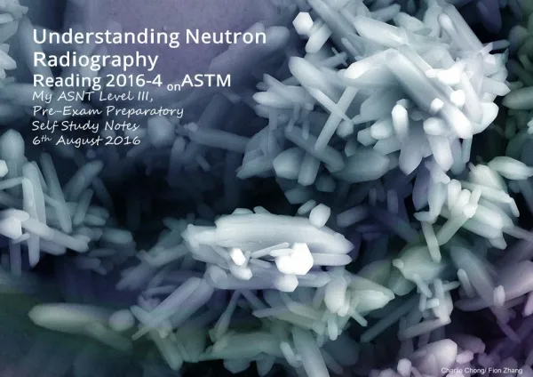
Understanding Neutron R adiography R eading 2016-4 onASTM My ASNT Level III, Pre-Exam Preparatory Self Study Notes 6thAugust 2016 Charlie Chong/ Fion Zhang
Spallation Neutron Source Charlie Chong/ Fion Zhang
Spallation Neutron Source Charlie Chong/ Fion Zhang
Spallation Neutron Source Charlie Chong/ Fion Zhang
Spallation Neutron Source Charlie Chong/ Fion Zhang http://www.acceleratorsamerica.org/resources/image-gallery/index.html
The Magical Book of Neutron Radiography Charlie Chong/ Fion Zhang
数字签名者:Fion Zhang DN:cn=Fion Zhang, o=Technical, ou=Academic, email=fion_zhang @qq.com, c=CN 日期:2016.08.08 10:30:04 +08'00' Charlie Chong/ Fion Zhang
ASNT Certification Guide NDT Level III / PdM Level III NR - Neutron Radiographic Testing Length: 4 hours Questions: 135 1. Principles/Theory • Nature of penetrating radiation • Interaction between penetrating radiation and matter • Neutron radiography imaging • Radiometry 2. Equipment/Materials • Sources of neutrons • Radiation detectors • Non-imaging devices Charlie Chong/ Fion Zhang
3. Techniques/Calibrations • Electron emission radiography • Blocking and filtering • Micro-radiography • Multifilm technique • Laminography (tomography) • Enlargement and projection • Control of diffraction effects • Stereoradiography • Panoramic exposures • Triangulation methods • Gaging • Autoradiography • Real time imaging • Flash Radiography • Image analysis techniques • In-motion radiography • Fluoroscopy Charlie Chong/ Fion Zhang
4. Interpretation/Evaluation • Image-object relationships • Material considerations • Codes, standards, and specifications 5. Procedures • Imaging considerations • Film processing • Viewing of radiographs • Judging radiographic quality 6. Safety and Health • Exposure hazards • Methods of controlling radiation exposure • Operation and emergency procedures Reference Catalog Number NDT Handbook, Third Edition: Volume 4, Radiographic Testing 144 ASM Handbook Vol. 17, NDE and QC 105 Charlie Chong/ Fion Zhang
Fion Zhang at Copenhagen Harbor 4thAugust 2016 Charlie Chong/ Fion Zhang
SME- Subject Matter Expert http://cn.bing.com/videos/search?q=Walter+Lewin&FORM=HDRSC3 https://www.youtube.com/channel/UCiEHVhv0SBMpP75JbzJShqw Charlie Chong/ Fion Zhang
Gamma- Radiography TABLE 1. Characteristics of three isotope sources commonly used for radiography. Source T½ Energy HVL Pb HVL Fe Specific Activity Dose rate* Co60 5.3 year 1.17, 1.33 MeV 12.5mm 22.1mm 50 Cig-1 1.37011 Cs137 30 years 0.66 MeV 6.4mm 17.2mm 25 Cig-1 0.38184 Ir192 75 days 0.14 ~ 1.2 MeV (Aver. 0.34 MeV) 4.8mm ? 350 Cig-1 0.59163 Th232 0.068376 Dose rate* Rem/hrat one meter per curie Charlie Chong/ Fion Zhang
八千里路云和月 Charlie Chong/ Fion Zhang
闭门练功 Charlie Chong/ Fion Zhang
Charlie Chong/ Fion Zhang http://greekhouseoffonts.com/
Designation: E 545 – 99 Standard Test Method for Determining Image Quality in Direct Thermal Neutron R adiographic Examination Charlie Chong/ Fion Zhang
1. Scope 1.1 This test method covers the use of an Image Quality Indicator (IQI) system to determine the relative quality of radiographic images produced by direct, thermal neutron radiographic examination (Gadolinium, Lithium, Samarium) . The requirements expressed in this test method are not intended to control the quality level of materials and components. 1.2 This standard does not purport to address the safety concerns, if any, associated with its use. It is the responsibility of the user of this standard to establish appropriate safety and health practices and determine the applicability of regulatory limitations prior to use. 1.3 The values stated in SI units are regarded to be standard. Charlie Chong/ Fion Zhang
2. R eferenced Documents 2.1 ASTM Standards: E 543 Practice for Agencies Performing Nondestructive Testing E 748 Practices for Thermal Neutron Radiography of Materials E 803 Method for Determining the L/D Ratio of Neutron Radiography Beams E 1316 Terminology for Nondestructive Examinations E 2003 Practice for Fabrication of Neutron Radiographic Beam Purity Indicators E 2023 Practice for Fabrication of Neutron Radiographic Sensitivity Indicators Charlie Chong/ Fion Zhang
3. Terminology 3.1 Definitions—For definitions of terms used in this test method, see Terminology E 1316, Section H. Charlie Chong/ Fion Zhang
4. Summary of Test Method 4.1 The judgment of the quality of a neutron radiograph is based upon the evaluation of images obtained from indicators that are exposed along with the test object. In cases of limited film size or extended object size, the indicators may be exposed on another film immediately prior to or following exposure of the test object under exactly the same conditions (refer to Process Control Radiographs, Section 10). The IQI values must be determined from films with an optical density between 2.0 to 3.0. Two types of IQIs are used. Charlie Chong/ Fion Zhang
IQI#1 4.1.1 Beam Purity Indicator (BPI) The BPI is a device used for quantitative determination of radiographic quality. It is a polytetrafluoroethylene block containing two boron nitride disks, two lead disks, and two cadmium wires. A key feature of the BPI is the ability to make a visual analysis of its image for subjective information, such as image unsharpness and film and processing quality. Densitometric measurements of the image of the device permit quantitative determination of the effective value for the: ■ thermal neutron content, ■ gamma content, ■ pair production content, and ■ scattered neutron content. The BPI shall be constructed in accordance with Practice E 2003. Optionally, any BPI fabricated prior to publication of Practice E 2003 which conforms to Test Method E 545 - 81 through 91 may be used. Charlie Chong/ Fion Zhang
BPI Charlie Chong/ Fion Zhang
BPI boron nitride disks lead disks polytetrafluoroethylene block cadmium wires Charlie Chong/ Fion Zhang
IQI#2 4.1.2 Sensitivity Indicator (SI) The SI is one of several devices used for qualitative determination of the sensitivity of detail visible on a neutron radiograph. The SI is a step-wedge device containing gaps and holes of known dimensions. Visual inspection of the image of this device provides subjective information regarding total radiographic sensitivity with respect to the step-block material. The SI shall be in accordance with Practice E 2023. Optionally, any SI fabricated prior to publication of Practice E 2023 which conforms to Test Method E 545-81 through 91 may be used. Charlie Chong/ Fion Zhang
SI Charlie Chong/ Fion Zhang
Methylmethacrylate Methylmethacrylate Charlie Chong/ Fion Zhang
NRT IQI 25mm Charlie Chong/ Fion Zhang
NRT IQI Al Methylmethacrylate Pb Charlie Chong/ Fion Zhang
25mm Charlie Chong/ Fion Zhang
4.2 Neutron radiography practices are discussed in Practices E 748. Charlie Chong/ Fion Zhang
5. Significance and Use 5.1 The BPI is designed to yield quantitative information concerning neutron beam and image system parameters that contribute to film exposure and thereby affect overall image quality. In addition, the BPI can be used to verify the day-to-day consistency of the neutron radiographic quality. Gadolinium conversion screens and single-emulsion silverhalide films, exposed together in the neutron imaging beam, were used in the development and testing of the BPI. Use of alternative detection systems may produce densitometric readings that are not valid for the equations used in Section 9. 5.2 The only truly valid sensitivity indicator is a reference standard part. A reference standard part is a material or component that is the same as the object being neutron radiographed except with a known standard discontinuity, inclusion, omission, or flaw. The sensitivity indicators were designed to substitute for the reference standard and provide qualitative information on: (1) hole and (2) gap sensitivity. Charlie Chong/ Fion Zhang
gap sensitivity hole sensitivity Methylmethacrylate Charlie Chong/ Fion Zhang
5.3 The number of areas or objects to be radiographed and the film acceptance standard used should be specified in the contract, purchase order, specification, or drawings. Charlie Chong/ Fion Zhang
6. Basis of Application 6.1 Qualification of Nondestructive Agencies—If specified in the contractual agreement, NDT agencies shall be qualified and evaluated in accordance with Practice E 543. The applicable revision of Practice E 543 shall be specified in the contractual agreement. 6.2 Procedures and Techniques—The procedures and techniques to be utilized shall be as described in this test method unless otherwise specified.Specific techniques may be specified in contractual documents. 6.3 Extent of Examination—The extent of examination shall be in accordance with Section 7 unless otherwise specified. 6.4 Reporting Criteria/Acceptance Criteria—Reporting criteria for the examination results shall be in accordance with Section 11 unless otherwise specified. Acceptance criteria (for example, for reference radiographs) shall be specified in thecontractual agreement. Charlie Chong/ Fion Zhang
7. Procedure 7.1 The direction of the beam of radiation should be as perpendicular as possible to the plane of the film. 7.2 Use Conversion screens that respond to neutrons of thermal energies, such as metallic gadolinium. 7.3 Each radiograph shall include a beam purity indicator and a sensitivity indicator (refer to Section 10 for exceptions). The indicators shall be located no less than 25 mm from any edge of the exposed area of the film when feasible. The indicators shall be located such that the image of the indicators on the film do not overlap the image of the object. 7.4 The SI should be oriented parallel to and as close as possible to the film. 7.5 The SI should be oriented such that its thickest step is not adjacent to the BPI or the objects being radiographed. 7.6 The BPI surface must be parallel against the film cassette face during exposure or density readings will be invalid. Charlie Chong/ Fion Zhang
SI Placement thickest step ≥25mm edge of the exposed area of the film Charlie Chong/ Fion Zhang
7.7 The cadmium wires in the BPI shall be oriented such that their longitudinal axis is perpendicular to the nearest film edge. 7.8 Measure the film densities using a diffuse transmission densitometer. The densitometer shall be accurate to ±0.02 density units. 7.9 For the purpose of determining image quality, the background optical density shall be between 2.0 and 3.0 measured at the hole in the center of the BPI. 2.0 ~ 3.0 ±0.02 H&D Charlie Chong/ Fion Zhang
BPI Placement 2.0 ~ 3.0 ±0.02 H&D ≥25mm edge of the exposed area of the film Charlie Chong/ Fion Zhang
7.10 The only true measurement of the beam uniformity is with a radiograph made without objects. Background film optical density in the range from 2.0 to 3.0 across the film should not vary more than 65 % from the numerical mean of five measurements: one measurement at the center and one measurement approximately 25 to 30 mm toward the center from each corner of the film. If the beam diameter is smaller than the film, the four outside measurements shall be taken 25 to 30 mm from the edge of the beam located at 90° intervals. D±0.65 H&D and D= 2~3H&D 25 ~ 30 mm Measurement points Charlie Chong/ Fion Zhang
7.10 The only true measurement of the beam uniformity is with a radiograph made without objects. Background film optical density in the range from 2.0 to 3.0 across the film should not vary more than 65 % from the numerical mean of five measurements: one measurement at the center and one measurement approximately 25 to 30 mm toward the center from each corner of the film. If the beam diameter is smaller than the film, the four outside measurements shall be taken 25 to 30 mm from the edge of the beam located at 90° intervals. 25 ~ 30 mm Measurement points Charlie Chong/ Fion Zhang
7.11 Radiographs shall be free of any blemish that may interfere with subsequent examination of the image. 7.12 Determine the: ■ thermal neutron content (NC), ■ scattered neutron content (S), ■ gamma content (g), and ■ pair production content (P) by densitometric analysis of the BPI image. Make a determination of the constituents of film exposure by measuring the densities in the BPI image as shown in Table 1. Calculate the various exposure contributors by the equations given in Section 9. Charlie Chong/ Fion Zhang
BPI- Beam Purity Indicator Methylmethacrylate / Polytetrafluoroethylene Charlie Chong/ Fion Zhang
TABLE 1 Definitions of D Parameters DB Film densities measured through the images of the boron nitride disks. DL Film densities measured through the images of the lead disks. DH Film density measured at the center of the hole in the BPI. DT Film density measured through the image of the polytetrafluoroethylene. ∆DLDifference between the DLvalues. ∆DBDifference between the two DBvalues. Charlie Chong/ Fion Zhang
TABLE 1 Definitions of D Parameters DB Film densities measured through the images of the boron nitride disks. DL Film densities measured through the images of the lead disks. DH Film density measured at the center of the hole in the BPI. DT Film density measured through the image of the polytetrafluoroethylene. ∆DLDifference between the DLvalues. ∆DBDifference between the two DBvalues. DL1 DL2 DH DB1 DB2 DT Charlie Chong/ Fion Zhang
Image of SI http://mae-legacy.engineering.osu.edu/labs/nars/ Charlie Chong/ Fion Zhang
7.13 Determine the sensitivity level by visually analyzing the image of the SI. Determine the values for G and H using Tables 2 and 3. 7.14 Determine the neutron radiographic category from Table 4. 7.15 Visually compare the images of the cadmium wires in the BPI. An obvious difference in image sharpness indicates an L/D ratio of 35 or less. Use Method E 803 for quantifying the L/D ratio. L/D ratio of 35 or less Charlie Chong/ Fion Zhang