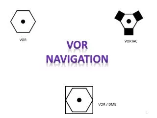
VOR Navigation
VOR Navigation. AST 241 Chapter 2. History. VOR’s derived from the old 4-course radio range from the late 1920’s and 1930’s Gained widespread use for navigation in the 1950’s Made instrument navigation commonplace

VOR Navigation
E N D
Presentation Transcript
VOR Navigation AST 241 Chapter 2
History • VOR’s derived from the old 4-course radio range from the late 1920’s and 1930’s • Gained widespread use for navigation in the 1950’s • Made instrument navigation commonplace • Remain the basis for most of the world’s air navigation systems- and will be for 5-10 yrs.
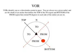
Principles of operation • VOR’s are commonly described as broadcasting 360 separate radials emanating from the station in all directions. • How do they really work? • VOR’s broadcast 2 signals- the reference (or 360-N) signal and the rotating signal.
Principles of Operation • If the two signals are in phase the aircraft is on the 360 “radial”, if the receiver detects these signals are out of phase by ¼ then the aircraft is located on the 90 “radial” from the station and so on.
Principles of operation • Remember the VOR “Omni” head in the aircraft only tells the pilot one thing which is? • Where the aircraft is located with respect to the selected radial- IF interpreted correctly. • No aircraft heading information (unless HIS) • No distance information
Principles of operation • What is the most important initial action when using a VOR for air navigation? • Tune and IDENTIFY the Station
VOR information • How is a VOR used to Determine which radial an aircraft is located on? • How is a VOR used to determine a heading to get to a particular station? • How Can the VOR receiver(s) be used to locate your relative position if lost?
VOR information • Most pilots are taught to use the VOR as a “command” instrument- “Which way do I fly?” • The VOR receiver was originally designed as a SHI- Station Heading Indicator.
SHI Steps: • Tune and identify the station • Put the desired radial at the top of the indicator and interpret where you are in relation to that selected course. • Use the CDI (course deviation indicator) and the TO/FROM flag to divide the VOR into quadrants. • The midpoint of the quadrant containing the CDI and the TO/FROM flag will give a 45 degree INBOUND intercept for the selected course.
SHI steps ctn. • The midpoint of the quadrant with the CDI but opposite the TO/FROM flag will give a 45 degree OUTBOUND intercept • REMEMBER- if after that you plan to track TO the station to orient the OMNI Head so that your aircraft heading and VOR indication are the same to avoid reverse sensing- Have a TO indication if going TO the station.
Tracking • All previous principles work well in a no-wind situation • Wind complicates the process in 3 ways: • The greater the distance from the station the slower the needle reacts (Fig. 2-11) • The stronger the cross-wind the greater the correction should be • The faster the aircraft the less the correction should be- less “relative” effect on the aircraft
Tracking • 2 Basic means of establishing track: • Bracketing and Estimating • Bracketing- logical trial & Error • The speed of needle drift is an indirect indication of the crosswind strength
Tracking • The 30 degree rule for tracking: • Make a 30 degree initial turn toward the needle (assuming correct orientation) • When the needle centers- remove ½ of the correction- 7-8 degrees. • Watch needle • If it drifts back in the direction of the original drift- add the 7-8 removed degrees back in and go 7-8 in the other direction
Tracking • If the needle drifts the other way take 8 degrees out. • Go through this iteration again using 3-4 degrees and then again with 1-2 degrees until a workable heading is found • *Then the wind will change!
Estimating • Estimating is essentially the same as tracking except you start with a pre-calculated value based on known wind information. • When using this method begin with 5 degree changes instead of the 15 degrees used when winds are not known.- this is generally a quicker method.
VOR testing • How often do VOR receivers have to be tested for tolerance for VFR flight? • How about for IFR flight? • Every 30 days- with a logbook entry give date, time/place, name & bearing error. • Many airports have VOT facilties • What are they and how do you know if they have one?
Testing • What is the allowable error if using a VOT? • +/- 4 degrees • What are the acceptable VOR indications when using a VOT? • 180-TO and 360- From • Some airports have certified VOR checkpoints on the field- refer the the AFD.
Testing • When using checkpoints what are the allowable tolerances? • Ground +/- 4 degrees • Flight +/- 6 degrees • You are allowed to make your own checkpoints • If tested against each other 2 receivers must be within ______ degrees? • 4 degrees
Testing • It is recommended that VOR’s be periodically calibrated as they may indicate correctly close to the station yet be out of tolerance when at a greater distance.
VOR range • The VOR transmission is limited to line of sight and can be disrupted by terrain- to avoid this stay on published airways or refer to the AFD • Remember the VOR accuracy is limited to 1 degree which may add up to a 28 mile discrepancy at 200 miles if the VOR is at the 4 degree max. tolerance.
VOR range • Terminal VOR (T)- from 1,000 ft. to 12,000 ft. out to 25 NM • Low Alt. (L)- from 1,000 ft. to 18,000 ft out to 40 NM • High Alt.(H)- from 1,000 ft. – 14,500 out to 40 NM, from 14,500ft. – 60,000 ft. out to 100 NM and from 18,000 ft. - 45,000 ft. out to 130 NM.