VOR NAVIGATION
VOR. VOR NAVIGATION . VORTAC. VOR / DME. VOR / DME Terminology. CDI – Course deviation indicator is a needle hinged to move laterally across the instrument face to show course deviation DME – Distance measuring equipment

VOR NAVIGATION
E N D
Presentation Transcript
VOR VOR NAVIGATION VORTAC VOR / DME
VOR / DME Terminology • CDI – Course deviation indicator is a needle hinged to move laterally across the instrument face to show course deviation • DME – Distance measuring equipment • HSI - combines the DG heading indicator with the CDI to provide better situational awareness of location with respect to the course line • TACAN - Military tactical air navigation (TACAN) equipment • VORTAC - When a TACAN is co-located with a VOR, it is known as a VORTAC • VOR is short for Very-High Frequency Omnidirectional Range • VOR / DME - When a DME station is co-located with a VOR, it is known as a VOR / DME • VOT - A VOT is a low-power VOR station that transmits only the 360° radial to use as a VOR receiver check • Phantom or Ghost VOR – Occurs when a TACAN is not frequency paired with a VOR, but a VOR frequency is presented to enable DME tuning – e.g., Ellington (EFD) ILS 17R EFD TAC 31 is on frequency (109.4)
VOR Station Signals • Two signals are transmitted from the ground station • Non-directional reference phase • Transmitted every time the variable phase transmission sweeps past magnetic north - 0° • Rotating variable phase • Transmits cyclically around the 360 degrees of the azimuth approximately 30 times per second • This signal is transmitted by the antennas circling around station • Both signals are transmitted 30 times per second • Radial information is derived by aircraft’s receiver from the difference in time between the two signals (which is different for each radial) – called phase difference • Courses oriented FROM the station are called radials • VOR operates in the 108 to 118Mhz VHF range • Low power – Generally 50 (terminal VOR) to 200W (high altitude) • VORs transmit “line of sight” • Lower you fly, the closer you must be to pick up a signal • Accuracy is within ± 1°
VOR Station Signals • VOR is oriented to magnetic north • BUT the VOR uses the variation that was established when the VOR was installed or last updated • Variation of the VOR is shown in the AFD Elevation of the VOR / Variation
VOR Station Signal Restrictions • Signals are not always available in all service areas • Check AFD • Check Notams Monitored status of VOR Unusable VOR areas Unusable DME areas Unusable TACAN areas
VOR Station SignalsUnmonitored VOR • VORs, VORTACs, and TACANs have an automatic course alignment and signal monitor (ACM). The ACM is usually connected to a remote alarm. When the ACM detects a malfunction, the unit switches to a standby transmitter. If the standby transmitter does not work properly, the facility will shut down. • “Unmonitored" means that there is no ability to observe the VOR’s operational status due to a problem or because the VOR was not designed to be monitored • An unmonitored VOR / DME is likely functioning normally • To use, tune and identify the unmonitored VOR • If a reliable signal is not received, notify ATC so they may confirm if the VOR is out-of-service • A reliable signal can be used – BUT maintain a constant listening watch on the frequency and vigilantly watch for flags • Remember, an airport may not be used for an alternate if the airport NAVAID is unmonitored
VOR Ground Station Classes "L" and "T" VORs have an (L) or (T) after the identifier on NACO Enroute High Altitude charts. "T" VORs on NACO Enroute Low Altitude charts have a (T) following the identifier. H and L classes are not differentiated on the chart. • LOW • From 1,000 feet AGL up to and including 18,000 feet AGL -> 40 NM. • HIGH • From 1,000 feet AGL up to and including 14,500 feet AGL -> 40 NM • From 14,500 AGL up to and including 60,000 feet -> 100 NM • From 18,000 feet AGL up to and including 45,000 feet AGL -> 130 NM. • TERMINAL • From 1,000 feet AGL up to and including 12,000 feet AGL -> 25 NM • Noted with (T), (L) and (H) on Jeppenroute charts in the VOR box
VOR Aircraft Equipment • Nav receiver and VOR indicator instrument (CDI display, HSI, RMI or glass cockpit display) • DME receiver • Can substitute GPS distance – BUT be careful measuring points may not be the same RMI CDI HSI
VOR Aircraft Equipment VOR Frequency Display – In use and stand-by Identification feature and volume control Tuning knob Some receivers will display the radial you are on
VOR Aircraft EquipmentVOR Indicator Instruments OBS Selected To/From indicator Course deviation indicator (CDI) CDI HSI OBS – or radial selector
VOR Aircraft Equipment Fly to the Bar! VOR Indicator’s three main parts: the Omni Bearing Selector (OBS) - rotating azimuth dial (Rotating Course Card) which provides for bearing selection the Course Deviation Indicator (CDI) - vertical needle that moves laterally along a row of dots, each dot representing 2°; the CDI can be centered by rotating the OBS; when this is done the aircraft position on the indicated VOR radial TO/FROM flag – Indicates whether the aircraft bearing is on the “to” or “from” side of the VOR
Radio Magnetic Indicator (RMI) • RMI is a bearing indicator • The bearing indicator (pointer) always points to the VOR station • The bearing indicator, in turn, is superimposed on an azimuth display that is virtually identical to the aircraft’s heading indicator • In the example to the right, the aircraft is flying a heading of 010°, the bearing to the VOR is 270°, and the aircraft is currently crossing the 090° Radial ADF VOR Pointer
VOR Aircraft Equipment • VOR indicator instrument Warning Flags • “OFF” flag • Indicates an usable or unreliable signal • Flag retracts from view when signal strength is sufficient for reliable indications • Nav radio may not be powered • Insufficient signal strength may also be indicated by a blank or OFF in the TO/FROM window
Radials • There are 360 radials radiating from the VOR • The CDI (needle) will center when you turn the OBS to the radial you are on and will have a FROM indication • The CDI (needle) will ALSO center AGAIN when you turn the OBS to the radial 180° from the one you are on. This radial will have a TO indication
Radials • Each radial represents 1° • How far apart are the radials? • At 60 NM from the station radials are 1 NM apart • Distance for crossing radials - Distance = (Miles from station / 60) X number of degrees difference between radials • E.g., -- (15 miles from station / 60) x (going from 090° radial to 080° radial or 10° difference) = 2.5 NM between the radials • Width of a radial increases with distance from the station • Hence CDI becomes “more sensitive” as you get closer to the station “Funnel effect” of the signal
Using the VOR SignalsDon’t Use the VOR Until you know it's working • Tune the VOR frequency on the aircraft’s receiver • Identify the VOR • Use the “indent” function on the receiver to hear the VOR Morse code identifier (three letters) • Dots and dashes are shown on IFR charts and approach plates • Confirm there is no failure flag and that the needle does not have erratic indications • DME coded identifier is transmitted once for every 3 or 4 times the VOR identifier transmits. About once every 30 seconds. DME identifier is also higher-pitched 1350 Hz compared with 1020 Hz for a VOR • Can also listen to DME identifier on the DME receiver in many cases • Test - Center the CDI and check that the selected heading changes by 10 degrees at full scale CDI deflection Failure flag
Interpreting – CDI Needle • The CDI needle represents the desired VOR “radial” under the course index • If the CDI is 1 dot off of the center, the airplane is 2° off the selected radial (if 5 dots per side are indicated) • The CDI will deflect to either side depending on how many degrees the aircraft is off the selected radial • Full deflection of the CDI from the selected radial indicates the aircraft is 10° or more from the selected radial Course Index Dots
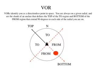
Interpreting – TO/FROM Flag • The TO / FROM flag reflects the aircraft’s position relative to a line through the VOR that is perpendicular to the radial shown under the index • In this case the perpendicular line runs from the 270° radial to the 090° radial • Which means the aircraft is on a radial from the 090° radial to the 270° radial on the bottom half of the instrument
Interpreting – TO/FROM Flag • The flag always indicates the course to the VOR! Assuming the aircraft is moving in the general direction of the OBS • A “TO” flag means the aircraft has not yet passed the VOR on that radial • A FROM flag, however, means the aircraft is past the station on the indicated radial and, if on that heading, moving further away • If the TO / FROM is blank or neutral, the aircraft is in the “zone of confusion” or on a radial perpendicular to the OBS (90° or 270° in this case)
Interpreting – TO/FROM Flag • If the TO Flag points down (from), the course to the station will be in the lower part of the instrument face (flying the course under the course index will take you away from the station) • If the TO Flag points up, the course to the station will be in the upper part of the instrument face as the plane is located in the lower part • When the CDI is centered, the course to the station is indicated either under the upper or lower course index of the instrument depending on the TO/FROM Flag • If the CDI is not centered then the course must be interpolated by the number of dots the CDI is off-center
Interaction of the CDI Needle and TO/FROM Flag • The course index defines the selected radial • The selected radial also sets which side the TO/FROM flag points to • When 150° course is changed to 330° course the FROM flag would show TO as the radial is changed 180 degrees – Note that the CDI also changes sides
Interpreting – Where Am I • The position of the aircraft in relation to the VOR station is always: • On the opposite side of the TO flag • On the opposite side of the CDI • The VOR is on the bearing of the OBS hdg ±CDI deviation • With a TO flag left is minus right is plus. • With a FROM flag left is plus and right is minus. • However, it is easier to look at the end of the CDI needle which is on the same side (top or bottom) as the VOR (indicated by the FLAG) and use that as an indicator of whether the radial is + or - the CDI needle Aircraft is in the lower right quadrant of the VOR - Station is ahead of the aircraft - Aircraft is to the right of the radial
Interpreting – Where Am IThinking in Quadrants • The CDI needle eliminates half of all possible headings to the station (Left or Right) • The TO / FROM indicator eliminates half of all possible headings to the station (Ahead or behind) • The result is that the VOR indicator instrument always provides the course to the station within ninety degrees -- "quadrature"
Interpreting – Where Am IThinking in Quadrants • The OBS in this example is tuned to the 150° radial • CDI needle shows that all headings intersecting the 150° radial lie on the left side of the OBS, between 150 and 330° • TO/FROM flag indicates that the headings to the station lie at the bottom of the OBS between 060 and 240° • Superimposing the two hemispheres, it is clear that the headings that intercept the 150° radial and fly toward the station lie between 060 and 330° • To intercept the 150° radial at a 45° angle and flying toward the station requires a course of 015° (60° - 45°) • Conversely, intercepting the 150° radial at a 45° angle and flying away from the station requires a course of 105° (60° + 45°)
Interpreting – Where Am IDirection of the Aircraft • The VOR will have the same indications regardless of which way the airplane’s nose is pointing • To keep the CDI needle indication moving in the correct direction • When flying to the station, the OBS should be tuned to the reciprocal of the desired radial to keep the heading to the station at the top of the VOR indicator instrument and on the side of the CDI • E.g., If flying inbound to the station on the 180° radial, the OBS should be tuned to the 360° radial • When flying away from the station, the OBS should be tuned to the radial on which you are departing from the station • E.g., If flying outbound from the station on the 180° radial, the OBS should be tuned to the 180° radial • If you set the OBS to the reciprocal of where it should be, the CDI will reflect reverse sensing. To correct for reverse sensing needle deflection you must fly away from the needle. • To avoid this reverse sensing situation, set the VOR to agree with your intended course.
Where Am I • To find the aircraft’s position relative to a VOR • Rotate the OBS until FROM appears in the window • Then center the CDI needle • The index line at the top of the instrument indicates the VOR radial on which the aircraft is located • The course to the VOR is the reciprocal of the radial on which the aircraft is located • With an RMI, the RMI needle tail will indicate which radial you are located on
Interpreting – Where Am I Located on same side of VOR hemisphere from the radial – hence “FROM” indication - VOR is behind the aircraft • VOR indicator instrument CDI display information has nothing to do with the heading of the aircraft! • Think of the four quadrants to understand where you are • In the example with the 030° radial selected (top of the Azimuth card) • Observe the CDI indications change based on which quadrant the aircraft is in • Aircraft orientation has no effect Selected radial CDI Needle shows direction to fly to reach the selected radial You are on the opposite side of VOR hemisphere from the radial – hence “TO” indication - VOR is in front of the aircraft
Interpreting – Where Am I FLY TOWARDS THE NEEDLE TO REACH THE COURSE • If the CDI is deflected to the right, it means the aircraft is to the left of course and you must fly to the right to intercept the 030° radial • This logic only works if the aircraft is oriented to the OBS selection CDI Needle shows direction to fly to reach the selected radial
Going Somewhere?Tracking and Homing • Keeping the CDI centered will take the aircraft to the station • To track to the station, the OBS value at the index is not changed • To track FROM the station: a) position the aircraft on the desired radial; b) center the CDI needle with a FROM indication; and c) fly the appropriate course to keep the CDI centered. If the CDI deflects, right or left, fly a corrective course towards the CDI needle to re-center the CDI • To home to the station, the CDI needle is periodically centered, and the new course under the index is used for the aircraft heading • Homing will follow a circuitous route to the station, just as with ADF homing. Tracking to the station is almost always used.
Going Somewhere?Intercepting a Course • Turn to a heading to roughly parallel your desired course • Rotate the OBS until the CDI needle centers with a TO flag showing for an inbound course or a FROM flag for a course away from the VOR • Note the number of degrees between the course which centers the CDI and your desired course • Double the difference to find an intercept angle • Angle should not be less than 20° or more than 90° • Rotate the OBS to the desired radial • Turn toward the CDI to your selected intercept angle • When the CDI begins to center you are closing in on the desired radial and should begin reducing the intercept angle to turn on the desired radial • Timing is key to avoid under or overshooting the desired radial • Can judge by the speed at which the CDI is moving towards the center
Going Somewhere?Intercepting a Course Reduce the intercept angle to turn on the desired radial Assume you are on the 160° radial and want to intercept a 025° course to track inbound to the station Compute intercept and then turn to the intercept heading Intercept Computation Rotate OBS to center it with TO flag (340°) Find degrees of difference between desired course and OBS (025° - 340° = 45° difference) Double the difference = 90° Rotate OBS to 025° Intercept course = 025°- 90° = 295° (this course can also be quickly seen at the 90° mark on the VOR instrument) Note: Can be easier to subtract 180 degrees initially and compute in the lower hemisphere Turn to a heading of 025° Inbound on the 160° radial – Heading 340°
Zone of Confusion • An inverted cone that is centered over the VOR is called the zone of confusion • In the zone of confusion the CDI needle becomes very sensitive and oscillates from side to side and may become unusable • You may see an off flag on the TO / FROM indicator or CDI • Cone gets smaller as your altitude above the station decreases
RadialsIdentifying an Intersection • You may need to identify an intersection of two VOR radials • where an airway changes heading • to intercept another airway • change in minimum altitude • holding point • reporting point for ATC • Intersection is identified by two VOR radials or sometimes one VOR radial and DME DME
RadialsIdentifying an Intersection • Tune and identify each station on a separate VOR • Set the OBS on each • Wait for both CDI needles to center and/or DME to be reached • Can also use 1 VOR switching between frequencies and radials
High Altitude VOR UseDME / RNAV Required • FAR 91.205(e) • If VOR navigation is used at or above FL 240 the aircraft must be equipped with approved DME or a suitable RNAV system • When the required DME or RNAV system fails at and above FL 240, the pilot in command of the aircraft must notify ATC immediately, and then may continue operations at and above FL 240 to the next airport of intended landing where repairs or replacement of the equipment can be made
VOR Operational Errors • Failure to properly identify a station • Failure to check the accuracy / sensitivity of the instrument • Turning in wrong direction from mis-perceived orientation • Failure to check ambiguity indicator, resulting in reverse sensing and corrections in the wrong direction • Failure to initially parallel desired radial on a track interception problem • Overshooting or undershooting radial on interception • Over-controlling corrections during tracking, especially close to the station when the CDI is very sensitive • Misinterpretation of station passage (voice transmission may cause transient fluctuation of TO/FROM indicator) • Chasing the CDI needle resulting in homing instead of tracking • Certain propeller RPM settings may cause CDI fluctuation of up to 6° (correct with slight RPM change)
Required VOR Equipment Checks • FAR 91.171 requires 30-day VOR checks if using VOR for IFR operations • Test Types • VOT – Must be within +/- 4° • Test signal – Radio repair station – Must be within +/- 4° • Surface Check point – Must be within +/- 4° - check can be done on the ground or in the air in many cases • If no VOT or surface checkpoint is available – then use an Airborne checkpoint - Must be within +/- 6° • If no VOT or checkpoint – then fly directly over a prominent ground point along a VOR radial that lies along the centerline of a VOR airway (preferably >20 miles from the VOR) and note the VOR indication - Must be within +/- 6° • If two independent VORs onboard the aircraft – Tune each VOR to the same station and center the CDI needles – Maximum differential between the indicated bearings cannot be more than 4° • Record the results in the aircraft log or other log • Date • Place • Bearing error • Signature of person conducting the check
VOR Test Facility (VOT) • The VOT transmits a signal which allows you to determine the operational status / accuracy of a VOR receiver: • on the ground • Some are available while in the air, but only in those areas and at the altitudes authorized in the A/FD or supplement • VOT locations are published in the A/FDon the applicable airport page and in the supplement • Two means of identification are used. • Morse code • Continuous tone • Information concerning a VOT’s test signal can be obtained from the local FSS • To use the VOT service: • Tune the VOT frequency on the VOR receiver • Center the CDI with a FROM indication • With the CDI centered, the OBS should read 0° with the TO/FROM indication showing FROM or 180°with TO showing in the TO/FROM indication. • An RMI should indicate 180° on any OBS setting
Certified VOR Checkpoint • Both airborne and ground checkpoints • Represent certified radials that should be received at specific points on the ground or over a specific landmark while airborne • Certified checkpoint locations are published in the A/FD supplement
DME Receiver DME receiver tuned frequency Remoted frequency Tuning / volume knob Ground speed / time functions Distance DME paired VOR frequency
DME Ground Station DME antenna
DME Characteristics • DME ground station is a separate piece of equipment with a separate antenna, even though paired with a VOR or TACAN • Aircraft DME unit (interrogator) generates a pulsed signal (interrogation) which is accepted by the DME ground station transceiver. • The DME station transceiver then generates pulsed signals (replies) that are sent back and accepted by the aircraft’s DME unit • Aircraft unit then computes distance by measuring the total round trip time of the interrogation and its reply • After two successful replies, a groundspeed can be calculated • DME Operates in the 962-1215 MHz (UHF) frequency band • BUT DME frequencies are paired with VOR frequencies; therefore, by selecting the VOR VHF signal, the appropriate UHF frequency is automatically selected in the DME equipment • System error (airborne and ground) is less than ±0.5 nm or 3 percent of the distance
DME Operation • DME displays distance from or to a ground station • Two types of ground stations • VOR-DME • VORTAC • Identification is the same as for the VOR, except that the code repeats only once every 30 seconds • Distance is slant range, thus at 6,000’ over the station the DME reads 1NM even though the plane is directly over the station • DME allows you to find a positive position fix with only one VOR, using radial + distance to define fix • Some receivers have ETA information, however the data is not accurate unless proceeding directly to the station The closer the airplane is to the DME station, the hypotenuse distance (slant range) is more affected by the vertical distance instead of the horizontal distance. DME error is greatest when the aircraft is high and close to the DME station.
TACAN • TACAN, is a navigation system created for military aircraft • More accurate version of the civilian DME system • DME portion of TACAN is available for civilian use at VORTACs • Can provide distance up to 390NM
Disclaimer • Instrument flight can be dangerous. Do not rely solely on this presentation – PROFESSIONAL INSTRUCTION IS REQUIRED • The foregoing material should not be relied upon for flight. • ALTHOUGH THE ABOVE INFORMATION IS FROM SOURCES BELIEVED TO BE RELIABLE SUCH INFORMATION HAS NOT BEEN VERIFIED, AND NO EXPRESS REPRESENTATION IS MADE NOR IS ANY TO BE IMPLIED AS TO THE ACCURACY THEREOF, AND IT IS SUBMITTED SUBJECT TO ERRORS, OMISSIONS, CHANGE.