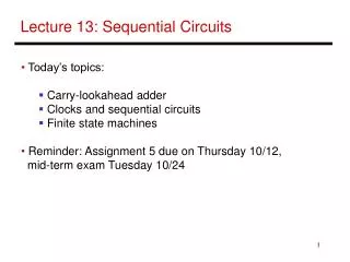
Lecture 13: Sequential Circuits
Lecture 13: Sequential Circuits. Today’s topics: Carry-lookahead adder Clocks and sequential circuits Finite state machines Reminder: Assignment 5 due on Thursday 10/12, mid-term exam Tuesday 10/24. Speed of Ripple Carry.

Lecture 13: Sequential Circuits
E N D
Presentation Transcript
Lecture 13: Sequential Circuits • Today’s topics: • Carry-lookahead adder • Clocks and sequential circuits • Finite state machines • Reminder: Assignment 5 due on Thursday 10/12, • mid-term exam Tuesday 10/24
Speed of Ripple Carry • The carry propagates thru every 1-bit box: each 1-bit box sequentially • implements AND and OR – total delay is the time to go through 64 gates! • We’ve already seen that any logic equation can be expressed as the • sum of products – so it should be possible to compute the result by • going through only 2 gates! • Caveat: need many parallel gates and each gate may have a very • large number of inputs – it is difficult to efficiently build such large • gates, so we’ll find a compromise: • moderate number of gates • moderate number of inputs to each gate • moderate number of sequential gates traversed
Computing CarryOut • CarryIn1 = b0.CarryIn0 + a0.CarryIn0 + a0.b0 • CarryIn2 = b1.CarryIn1 + a1.CarryIn1 + a1.b1 • = b1.b0.c0 + b1.a0.c0 + b1.a0.b0 + • a1.b0.c0 + a1.a0.c0 + a1.a0.b0 + a1.b1 • … • CarryIn32 = a really large sum of really large products • Potentially fast implementation as the result is computed • by going thru just 2 levels of logic – unfortunately, each • gate is enormous and slow
Generate and Propagate Equation re-phrased: ci+1 = ai.bi + ai.ci + bi.ci = (ai.bi) + (ai + bi).ci Stated verbally, the current pair of bits will generate a carry if they are both 1 and the current pair of bits will propagate a carry if either is 1 Generate signal = ai.bi Propagate signal = ai + bi Therefore, ci+1 = gi + pi . ci
Generate and Propagate c1 = g0 + p0.c0 c2 = g1 + p1.c1 = g1 + p1.g0 + p1.p0.c0 c3 = g2 + p2.g1 + p2.p1.g0 + p2.p1.p0.c0 c4 = g3 + p3.g2 + p3.p2.g1 + p3.p2.p1.g0 + p3.p2.p1.p0.c0 Either, a carry was just generated, or a carry was generated in the last step and was propagated, or a carry was generated two steps back and was propagated by both the next two stages, or a carry was generated N steps back and was propagated by every single one of the N next stages
Divide and Conquer • The equations on the previous slide are still difficult to implement as • logic functions – for the 32nd bit, we must AND every single propagate • bit to determine what becomes of c0 (among other things) • Hence, the bits are broken into groups (of 4) and each group • computes its group-generate and group-propagate • For example, to add 32 numbers, you can partition the task as a tree . . . . . . . . . . . . . . . . . . . . .
P and G for 4-bit Blocks • Compute P0 and G0 (super-propagate and super-generate) for the • first group of 4 bits (and similarly for other groups of 4 bits) • P0 = p0.p1.p2.p3 • G0 = g3 + g2.p3 + g1.p2.p3 + g0.p1.p2.p3 • Carry out of the first group of 4 bits is • C1 = G0 + P0.c0 • C2 = G1 + P1.G0 + P1.P0.c0 • … • By having a tree of sub-computations, each AND, OR gate has few • inputs and logic signals have to travel through a modest set of • gates (equal to the height of the tree)
Example Add A 0001 1010 0011 0011 and B 1110 0101 1110 1011 g 0000 0000 0010 0011 p 1111 1111 1111 1011 P 1 1 1 0 G 0 0 1 0 C4 = 1
Carry Look-Ahead Adder • 16-bit Ripple-carry • takes 32 steps • This design takes • how many steps?
Clocks • A microprocessor is composed of many different circuits • that are operating simultaneously – if each circuit X takes in • inputs at time TIX, takes time TEX to execute the logic, • and produces outputs at time TOX, imagine the • complications in co-ordinating the tasks of every circuit • A major school of thought (used in most processors built • today): all circuits on the chip share a clock signal (a • square wave) that tells every circuit when to accept • inputs, how much time they have to execute the logic, and • when they must produce outputs
Clock Terminology Rising clock edge Cycle time Falling clock edge 4 GHz = clock speed = 1 = 1 . cycle time 250 ps
Sequential Circuits • Until now, circuits were combinational – when inputs change, the • outputs change after a while (time = logic delay thru circuit) Combinational Circuit Combinational Circuit Outputs Inputs • We want the clock to act like a start and stop signal – a “latch” is • a storage device that stores its inputs at a rising clock edge and • this storage will not change until the next rising clock edge Clock Clock Combinational Circuit Combinational Circuit Outputs Inputs Latch Latch
Sequential Circuits • Sequential circuit: consists • of combinational circuit and • a storage element • At the start of the clock • cycle, the rising edge • causes the “state” storage • to store some input values • This state will not change for an entire cycle (until next rising edge) • The combinational circuit has some time to accept the value • of “state” and “inputs” and produce “outputs” • Some of the outputs (for example, the value of next “state”) may feed • back (but through the latch so they’re only seen in the next cycle Inputs State Clock Outputs Inputs Combinational Cct
Designing a Latch • An S-R latch: set-reset latch • When Set is high, a 1 is stored • When Reset is high, a 0 is stored • When both are low, the previous state is preserved (hence, known as a storage or memory element) • When both are high, the output is unstable – this set of inputs is therefore not allowed Verify the above behavior!
D Latch • Incorporates a clock • The value of the input D signal (data) is stored only when the clock • is high – the previous state is preserved when the clock is low
D Flip Flop • Terminology: • Latch: outputs can change any time the clock is high (asserted) • Flip flop: outputs can change only on a clock edge • Two D latches in series – ensures that a value is stored only on • the falling edge of the clock
Sequential Circuits • We want the clock to act like a start and stop signal – a “latch” is • a storage device that stores its inputs at a rising clock edge and • this storage will not change until the next rising clock edge Clock Clock Combinational Circuit Combinational Circuit Outputs Inputs Latch Latch
Finite State Machine • A sequential circuit is described by a variation of a truth • table – a finite state diagram (hence, the circuit is also • called a finite state machine) • Note that state is updated only on a clock edge Next state Next-state Function Current State Clock Output Function Outputs Inputs
State Diagrams • Each state is shown with a circle, labeled with the state • value – the contents of the circle are the outputs • An arc represents a transition to a different state, with the • inputs indicated on the label D = 0 D = 1 This is a state diagram for ___? D = 1 0 1 0 1 D = 0
3-Bit Counter • Consider a circuit that stores a number and increments the value on • every clock edge – on reaching the largest value, it starts again from 0 • Draw the state diagram: • How many states? • How many inputs?
3-Bit Counter • Consider a circuit that stores a number and increments the value on • every clock edge – on reaching the largest value, it starts again from 0 • Draw the state diagram: • How many states? • How many inputs? 000 001 010 011 100 101 110 111 000 001 010 011 100 101 110 111
Traffic Light Controller • Problem description: A traffic light with only green and red; either the • North-South road has green or the East-West road has green (both • can’t be red); there are detectors on the roads to indicate if a car is • on the road; the lights are updated every 30 seconds; a light need • change only if a car is waiting on the other road • State Transition Table: • How many states? • How many inputs? • How many outputs?
State Transition Table • Problem description: A traffic light with only green and red; either the • North-South road has green or the East-West road has green (both • can’t be red); there are detectors on the roads to indicate if a car is • on the road; the lights are updated every 30 seconds; a light must • change only if a car is waiting on the other road • State Transition Table: • CurrState InputEW InputNS NextState=Output • N 0 0 N • N 0 1 N • N 1 0 E • N 1 1 E • E 0 0 E • E 0 1 N • E 1 0 E • E 1 1 N
State Diagram State Transition Table: CurrState InputEW InputNS NextState=Output N 0 0 N N 0 1 N N 1 0 E N 1 1 E E 0 0 E E 0 1 N E 1 0 E E 1 1 N
Title • Bullet