Download
1 / 61
610 likes | 807 Vues
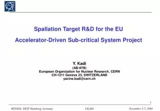
Spallation Target R&D for the EU Accelerator-Driven Sub-critical System Project. Y. Kadi (AB/ATB) European Organization for Nuclear Research, CERN CH-1211 Geneva 23, SWITZERLAND yacine.kadi@cern.ch. ISOL thick target. UC 2 target.

E N D
Spallation Target R&D for the EUAccelerator-Driven Sub-critical System Project Y. Kadi (AB/ATB) European Organization for Nuclear Research, CERN CH-1211 Geneva 23, SWITZERLAND yacine.kadi@cern.ch
ISOL thick target UC2 target Mass-Separation IonisationEffusionDiffusionNuclear reaction RILIS laser beams Time Nb cavity Transfer line UC2 pills Graphite sleeve Tantalum oven
ISOL targets materialsspallation - fission Z Users’ request frequency Refractory compounds: Oxides, carbides, chlorides Molten metals, Molten salts, Thins foils, powders Target thickness: 4-220 g/cm2
High energy protons fission of 238U and n-induced fission of 235U Fragments Spallation Fission
ISOLDE target handling. Class A laboratory (2004) SIsotopes(Activity/LA) > 10’000
Use of Spallation Neutrons • Spallation neutrons can be used to transmute the highly-radiotoxic nuclei which are present in nuclear waste into stable or very short lived isotopes that can be disposed off safely. • The techniques developed for ADS can be applied to optimize the production of fission products of the EURISOL-DS. ……. A long way to go but clear synergies in the neutronics …….
Transmutation of Nuclear Waste ? • Europe : 35% of electricity from nuclear energy • produces about 2500 t/y of used fuel: 25 t (Pu), 3.5 t (MAs: Np, Am, Cm) and 3 t (LLFPs). • social and environmental satisfactory solution is needed for the waste problem • The P&T in association with the ADS can lead to this acceptable solution.
Sub-Critical Systems (1) • In Accelerator-Driven Systems a Sub-Critical blanket surrounding the spallation target is used to multiply the spallation neutrons.
Sub-Critical Systems (2) ADS operates in a non self-sustained chain reaction mode minimises criticality and power excursions ADS is operated in a sub-critical mode stays sub-critical whether accelerator is on or off extra level of safety against criticality accidents The accelerator provides a control mechanism for sub-critical systems more convenient than control rods in critical reactor safety concerns, neutron economy ADS provides a decoupling of the neutron source (spallation source) from the fissile fuel (fission neutrons) ADS accepts fuels that would not be acceptable in critical reactors Minor Actinides High Pu content LLFF...
The Energy Amplifier Concept (2) Method: A high energy proton beam interacts in a molten lead (Pb-Bi) swimming pool. Neutrons are produced by the so-called spallation process. Lead is “transparent” to neutrons. Single phase coolant, b.p. ≈ 2000 °C TRU: They are introduced, after separation, in the form of classic, well tested “fuel rods”. Fast neutrons, both from spallation and fission, drift to the TRU rods and fission them efficiently. A substantial amount of net power is produced (up to ≈ 1/3 of LWR), to pay for the operation. LLFF: Neutrons leaking from the periphery of the core are used to transmute also LLFF (Tc99, I129 ....) Safety: The sub-criticality (k ≈ 0.950.98) condition is guaranteed at all times.
The Three Levels of ADS Validation Three different levels of validation of an ADS can be specified: • First, validation of the different component concepts, taken separately (accelerator, target, subcritical core, dedicated fuels and fuel processing methods). In Europe: The FEAT, TARC & MUSE experimental programs and the MEGAPIE project are significant examples. • Second, validation of the coupling of the different components in a significant environment, e.g. in terms of power of the global installation, using as far as possible existing critical reactors, to be adapted to the objectives. • Third, validation in an installation explicitly designed for demonstration (e.g. the ADS installation described in the European roadmap established by the Technical Working Group, chaired by prof. Rubbia). This third step should evolve to a demonstration of transmutation fuels, after a first phase in which the subcritical core could be loaded with “standard” fuel.
ADS VALIDATION: Level 1 • Physics Basic underlying physics has been thoroughly checked at zero power in particular by experiments at CERN and elsewhere Spallation process and neutron yields with proton beam in a wide range of energies Fission rates and lead nuclear properties: a sub-critical arrangement with k≈0.9 has demonstrated energy gain in agreement with calculations (FEAT Experiment) Transmutation rates for most offending LLFP. Fast elimination by “adiabatic resonance crossing” has been demonstrated experimentally for 129I and 99Tc. (TARC Experiment) Most key reactions fully tested at low power level A comprehensive programme of neutron induced cross-section measurements has been started (nTOF Project)
ADS VALIDATION: The TARC Experiment (1) Simulation of neutrons produced by a single 3.5 GeV/c proton (147 neutrons produced, 55035 scattering)
ADS VALIDATION: Level 1 • We are now at a turning point in terms of programme co-ordination and resource deployment in Europe. For the coming five to seven years, the R&D should concentrate on: • The development of high intensity accelerators and megawatt spallation sources, and their integration in a fissile facility • The development of advanced fuel reprocessing technology Throughout Europe, the main facilities or experiments of relevance are: • IPHI (High Intensity Proton Injector) in France and TRASCO (TRAsmutazione SCOrie) in Italy, on the design of a high current and reliable proton linear accelerator. • MEGAPIE (MEGAwatt PIlot Experiment), a robust and efficient spallation target, integrated in the SINQ facility at the Paul Scherrer Institute in Switzerland. The SINQ facility is a spallation neutron source fed by a 590 MeV proton cyclotron.
ADS VALIDATION: Level 1 • MUSE-4 (At the MASURCA installation in CEA-Cadarache, using the GENEPI Accelerator), as a first image of a sub-critical fast core fed by external neutrons. • JRC-ITU The Minor Actinide (fuel fabrication) and advanced aqueous and pyro-processing Laboratories at JRC-ITU in Karlsruhe. • JRC-IRMMNeutron data activity at Gelina TOF Facility in Geel. • N_TOF (Neutron Time of Flight) experiment at CERN, Geneva, for nuclear cross-section measurements. • KALLA (KArlsruhe Lead LAboratory) and • CIRCE (CIRCuito Eutettico) facilities for Pb and Pb-Bi Eutectic technology development in Brasimone, Italy.
ADS VALIDATION: MEGAPIE test • MEGAPIE Project at PSI • 0.59 GeV proton beam • 1 MW beam power • Goals: • Demonstrate feasablility • One year service life • Irradiation in 2005 Proton Beam
The Three Levels of ADS Validation Three different levels of validation of an ADS can be specified: • First, validation of the different component concepts, taken separately (accelerator, target, subcritical core, dedicated fuels and fuel processing methods). In Europe: The MUSE experimental program and the MEGAPIE project are significant examples. • Second, validation of the coupling of the different components in a significant environment, e.g. in terms of power of the global installation, using as far as possible existing critical reactors, to be adapted to the objectives. • Third, validation in an installation explicitly designed for demonstration (e.g. the ADS installation described in the European roadmap established by the Technical Working Group, chaired by prof. Rubbia). This third step should evolve to a demonstration of transmutation fuels, after a first phase in which the subcritical core could be loaded with “standard” fuel.
ADS VALIDATION Level 2: TRADE Project • The TRADE experiment suggested by C. Rubbia, first worked-out in an ENEA/CEA/CERN feasibility study and presently assessed by a wider international group (lead: ENEA, CEA, DOE, FZK), is a significant step towards the ADS demonstration, i.e. within the second step of ADS validation • Coupling of a proton accelerator to a power TRIGA Reactor via a spallation target, inserted at the center of the core. • Range of power : • in the core : 200 - 1000 KW, • in the target : 20 - 100 KW. • The main interest of TRADE, as compared to the MUSE experiments, is the ability of incorporating the power feedback effects into the dynamics measurements in ADS and to address ADS operational, safety and licensing issues.
The TRADE Facility - Reactor and Accelerator Buildings Control Room Window Cyclotron (section) Beam Pipe Core Reactor Shielded Beam Pipe Tunnel
Overall Lay-out of the TRADE Facility Top view & bending magnets Core cross-section
The main characteristics of TRADE • A proton cyclotron delivering a beam of 140 MeV protons (option investigated 300 MeV). • A three sections beam transport line: Matching section/Straight transfer line/Final bending line. • A solid Ta target (back-up : W clad in Ta). • Forced convection of the target cooling with a separate loop. • Natural convection for the core cooling. • Range of subcritical levels : k = 0.90 0.99
Primary Flux Thick Ta Target (protons/cm2/s) per mA - 140 MeV -
Primary Flux Thick Ta Target (protons/cm2/s) per mA - 300 MeV -
Radiation Damage Gas production and the displacement rates per kW of beam
Target cooling system in forced convection • Coarse Dimensioning of the circuit: • Thermal power = 40kW • Design ΔT ~ 5 - 20 °C • Pumps and circuit characteristics: • Pumps flow-rate ~ 8 - 2 m3/h • Water max speed (3 holes of Φ = 18 mm) ~ 3 - 1 m/s
Target cooling system in forced convection In presence of the design mass flow-rate of water (2.24 Kg/s), the maximum thermal flux at the outer wall of the target is 135 w/cm2 thus assuring a margin large enough to prevent the occurrence of Critical Heat Flux. Moreover the maximum temperature is 80°C which is significantly lower than the TRIGA saturation temperature
The Three Levels of ADS Validation Three different levels of validation of an ADS can be specified: • First, validation of the different component concepts, taken separately (accelerator, target, subcritical core, dedicated fuels and fuel processing methods). In Europe: The MUSE experimental program and the MEGAPIE project are significant examples. • Second, validation of the coupling of the different components in a significant environment, e.g. in terms of power of the global installation, using as far as possible existing critical reactors, to be adapted to the objectives. • Third, validation in an installation explicitly designed for demonstration (e.g. the ADS installation described in the European roadmap established by the Technical Working Group, chaired by prof. Rubbia). This third step should evolve to a demonstration of transmutation fuels, after a first phase in which the subcritical core could be loaded with “standard” fuel.
Spallation Target: Boundary Conditions • 350 MeV, 5 mA proton beam for fast neutron fluxes for transmutation, i.e. 1.75 MW of which 80 % is heat • 130 mm penetration depth for 350 MeV - Bragg peak • 72 mm ID radial extent of the beam tube + 122 mm OD radial extent of the feeder - limited by neutronics • Windowless target due to high beam load - despite vacuum • Pb-Bi because of neutronic and thermal properties MYRRHA Project: 50 - 80 MWth (k≈0.97) • 1.4 MW heat in ~ 0.5 l to be removed while meeting thermal and vacuum requirements
Spallation Target: Desired Target Configuration BEAM Fast core Volume-minimized recirculation zone gets lower ‘tailored’ heat input Example of radial tailoring Irradiation samples High-speed flow (2.5 m/s)permits effective heat removal
Spallation Target:Design and R&D Approach Interaction between: • Experiments with increasing complexity and correspondence to the real situation (H2O–Hg–PbBi) • CFDsimulations to • predict experimental results • optimize nozzles for experiments • simulate heat deposition which can not yet be simulated experimentally
Hg Experiments at IPUL • 8 ton Hg • Q up to 11 l/s • Vacuum above free surface < 0.1 mbar • Minimal pump load is necessary (to avoid pump cavitation) • Main flow • Adding/Removing Hg from cylinder • Vacuum system
60 16.5° DG16.5 Hg Experiments nominal volume flow 10 l/s Close to desired configuration ! • intermediate lowering of level • some spitting • axial asymmetry