Download
1 / 16
160 likes | 411 Vues
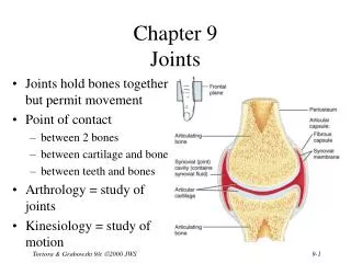
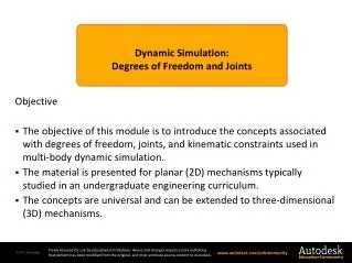
Dynamic Simulation : Degrees of Freedom and Joints. Objective The objective of this module is to introduce the concepts associated with degrees of freedom, joints, and kinematic constraints used in multi-body dynamic simulation.

E N D
Dynamic Simulation: • Degrees of Freedom and Joints Objective • The objective of this module is to introduce the concepts associated with degrees of freedom, joints, and kinematic constraints used in multi-body dynamic simulation. • The material is presented for planar (2D) mechanisms typically studied in an undergraduate engineering curriculum. • The concepts are universal and can be extended to three-dimensional (3D) mechanisms.
Degrees of Freedom (DOF) Section 4 – Dynamic Simulation Module 2 – DOF & Joints Page 2 • The independent parameters used to uniquely define the position and orientation of a part in space are called the degrees-of-freedom (DOF). • In three-dimensional space six DOF are required; three coordinates to define a location and three orientation angles. • Each DOF can have motion associated with it. y x z
Planar Systems Section 4 – Dynamic Simulation Module 2 – DOF & Joints Page 3 • A planar mechanism is one that has all parts constrained to move in a plane. • Constraining a part to a plane removes three degrees of freedom. • The part in the figure is part of a planar mechanism. It can have no motion in the global Z direction and no rotations about the local x & y axes. • A part constrained to move in a plane has three degrees-of-freedom. Y x y X Z
Body Fixed Coordinate System Section 4 – Dynamic Simulation Module 2 – DOF & Joints Page 4 • A body fixed coordinate system is used to define the DOF’s of a part. • A body fixed coordinate system is rigidly fixed to the body. • In a rigid body no point in the body moves relative to the body fixed coordinate system. • The origin of the coordinate system is located at the center-of-gravity. • The axes are oriented along the principle axes of inertia. Y Principal Axes of Inertia x y C.G. X
Position Constraints Section 4 – Dynamic Simulation Module 2 – DOF & Joints Page 5 • Position constraints impose conditions on the location and orientation of the part. • In the figure, a constraint is given to each DOF. • The constraints can be written in equation form as: • In this example, the constraint equations are not a function of time and the part is fixed in space (grounded). Y x y Ycg=15 X Xcg=20
Kinematic (Joint) Constraints Section 4 – Dynamic Simulation Module 2 – DOF & Joints Page 6 Kinematic constraints impose conditions on the relative motion between a pair of bodies. Kinematic constraints remove DOF’s from the assembly. In this example, the addition of constraints at the end of the link changes it from an object that is free to move in two directions and rotate to an object that can only rotate. Unconstrained Link with 3 DOF Constrained Link with 1 DOF
Mobility Section 4 – Dynamic Simulation Module 2 – DOF & Joints Page 7 • Mobility is the number of unconstrained DOF’s in a mechanism. • Each planar body starts out with three DOF’s. • Constraints eliminate some of these DOF’s until only a small subset are left. • The number of DOF’s in the subset is the mobility of the mechanism. • The number of actuators required to control the mechanism is equal to the mobility. coupler follower crank This four-bar mechanism has a mobility of one. The position of the coupler and follower can be computed if the angular position of the crank is specified.
Section 4 – Dynamic Simulation Module 2 – DOF & Joints Page 8 A revolute and prismatic joint are commonly used joints in planar mechanisms. A revolute and prismatic joint remove two DOF from a pair of parts in a planar mechanism. Revolute and prismatic joints are also common in 3D mechanisms. Common Joints Revolute Joint Prismatic Joint Allows two parts to rotate relative to each other about a shared axis. Allows two parts to translate relative to each other along a shared axis. http://upload.mcgill.ca/cden/MECH572-lecture5.ppt
Section 4 – Dynamic Simulation Module 2 – DOF & Joints Page 9 Gruebler’s equation can be used to determine the mobility of planar mechanisms. L = 2 J = 1 G = 1 DOF = 1 Link 1 3 DOF Gruebler’s Equation Gruebler’s Equation DOF = mobility L = number of links J = number of revolute joints or prismatic joints G = number of grounded links DOF = 3*L – 2* J – 3 *G = 3 (L-1) – 2 * J 1 DOF Link 2 3 DOF The revolute joint removes 2 DOF and the grounded link removes 3 DOF.
Mobility of Vise Grip Pliers Section 4 – Dynamic Simulation Module 2 – DOF & Joints Page 10 This example applies Gruebler’s equation to the determine the mobility of a vise grip plier. Each revolute joint removes two DOF. The screw joint removes two DOF. 1 5 4 1 L = 5 J = 4 (revolute) J = 1 (screw) G = 1 (your hand) 3 4 2 3 2 DOF = 3*5 - 2*5- 1*3 = 2 The mobility of the plier is two. Link 3 can be moved relative link1 when you squeeze your hand and the jaw opening is controlled by rotating link 5.
Welded Joints Section 4 – Dynamic Simulation Module 2 – DOF & Joints Page 11 • It is common for parts in a mechanism to be designed to move together. • In the figure, the bottom retainer, valve guide, and valve guide seal do not move relative to each other. • Similarly, the valve stem cup, valve cap, top retainer, keepers, and valve do not move relative to each other. • A joint that allows no relative motion is called a welded joint. Valve Stem Cup Valve Cap Upper Retainer Keepers Valve Valve Spring Valve Guide Seal Valve Guide Bottom Retainer Engine Block
Ground Joints Section 4 – Dynamic Simulation Module 2 – DOF & Joints Page 12 • One or more parts in a mechanism must be anchored to something rigid that holds it in place. • The anchored parts have all degrees of freedom removed. • A joint that removes all DOF’s by setting the coordinates and orientation angles equal to constant values are called Ground Joints. • In the figure, all moveable parts will move relative to the engine block that is fixed by a Ground Joint. Valve Stem Cup Valve Cap Upper Retainer Keeper x 2 Valve Valve Spring Valve Guide Seal Valve Guide Bottom Retainer Engine Block
Joint Types in Dynamic Simulation Section 4 – Dynamic Simulation Module 2 – DOF & Joints Page 13 • The Dynamic Simulation browser contains information about the types of joints used in a simulation. • Grounded parts are fixed in space and cannot move. • Mobile groups are parts or groups of parts that can move relative to each other • Welded groups contain a list of parts that are joined together. • Standard joints include common joints such as revolute, prismatic, etc.
Automatic Creation of Joints Section 4 – Dynamic Simulation Module 2 – DOF & Joints Page 14 • Dynamic Simulation operates on assemblies created in the Assembly environment. • The parts in an assembly have constraints that keeps them in the correct position relative to each other. • The assembly constraints are interpreted and converted to kinematic constraints in the Dynamic Simulation environment. The Insert constraint would be used in the Assembly environment to create this joint. It would automatically be converted to a revolute joint in the Dynamic Simulation environment.
Automatic Conversion Control Section 4 – Dynamic Simulation Module 2 – DOF & Joints Page 15 • The Dynamic Simulation environment allows joints automatically created from the assembly constraints to be turned off and on. • When the automatic conversion is turned off, all standard joints are deleted (including any that were manually created).
Module Summary Section 4 – Dynamic Simulation Module 2 – DOF & Joints Page 16 • This module presented the concepts associated with degrees-of-freedom, mobility of a mechanism, and joints used in multi-body dynamics. • It showed examples of how the concepts are incorporated into Dynamic Simulation. • These concepts will be used in subsequent modules that deal with multi-body dynamics theory and its practical implementation in Dynamic Simulation.