Advanced Machining Processes
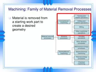
Advanced Machining Processes. Manufacturing Processes. Outline. Chemical Milling Photochemical Blanking Electrochemical Machining Pulsed Electrochemical Machining Electrochemical Grinding Electrical-Discharge Machining Electrical-Discharge Grinding Electrical-Discharge Wire Cutting

Advanced Machining Processes
E N D
Presentation Transcript
Advanced Machining Processes Manufacturing Processes
Outline • Chemical Milling • Photochemical Blanking • Electrochemical Machining • Pulsed Electrochemical Machining • Electrochemical Grinding • Electrical-Discharge Machining • Electrical-Discharge Grinding • Electrical-Discharge Wire Cutting • Laser-Beam Machining • Electron Beam Machining • Plasma Arc Cutting • Water Jet Machining • Abrasive Water Jet Machining • Abrasive Jet Machining
Chemical Milling Produces shallow cavities on a workpiece, usually to reduce weight The area affected by the chemical reagent is controlled by masking or by partial immersion
Chemical Milling Procedure: • Relieve residual stresses to prevent warping • Clean the material surface • Apply masking material • Remove the masking on regions that require etching • Apply the reagents • Wash the part • Remove remaining masking • Additional finishing or chemical milling procedures may be used
Photochemical Blanking Uses chemicals and photographic processes to remove material, usually from a thin sheet Can produce complex shapes on metals as thin as .0025 mm without forming burrs
Photochemical Blanking Procedure: • Prepare the design at a magnification of up to 100x; make a photographic negative and reduce it to the size of the part • Coat the blank with photosensitive material • Place the negative over the part and expose it to ultraviolet light to harden the exposed photosensitive coating • Dissolve the unexposed coating • Apply the chemical reagent • Remove the masking and wash the part
Chemical Machining Design Considerations: • Avoid sharp corners, deep narrow cavities, steep tapers, folded seams and porous workpieces • Undercuts may develop • Most of the workpiece should be shaped by other processes to speed production • Variations may occur depending onhumidity and temperature • Computerized designs must be converted to a format compatible with the photochemical artwork equipment
Electrochemical Machining Uses an electrolyte and electrical current to ionize and remove metal atoms Can machine complex cavities in high-strength materials Leaves a burr-free surface Not affected by the strength, hardness or toughness of the material
Electrochemical Machining Design Considerations: • The electrolyte erodes away sharp profiles • It is difficult to control electrolyte flow; irregular cavities may not be formed accurately • Allow for small taper in holes made this way
Pulsed Electrochemical Machining A form of electrochemical machining; the current is pulsed to eliminate the need for high electrolyte flow Improves fatigue life of the part
Electrochemical Grinding Uses a rotating cathode embedded with abrasive particles for applications comparable to milling, grinding and sawing Most of the metal removal is done by the electrolyte, resulting in very low tool wear Adaptable for honing
Electrochemical Grinding Design Considerations: (in addition to those for electrochemical machining) • Avoid sharp inside radii • Flat surfaces to be ground should be narrower than the width of the grinding wheel
Electrical-Discharge Machining Uses a shaped electrode and electric sparks to remove metal; discharges sparks at about 50-500 kHz A dielectric (nonconductive) fluid removes debris and acts as an insulator until the potential difference is high enough Can be used on any material that conducts electricity
Electrical-Discharge Machining Design Considerations: • Design parts so that the electrodes can be made economically • Avoid deep slots and narrow openings • Do not require very fine surface finish • Most of the material removal should be done by other processes to speed production
Electrical-Discharge Grinding The grinding wheel lacks abrasives and removes material by electrical discharges Can be combined with electrochemical grinding Can be used for sawing, in which the saw has no teeth
Electrical-Discharge Wire Cutting The wire moves through the workpiece like a band saw, removing material by electrical discharge Dielectric fluid is applied to the work area The wire is generally used only once; it is inexpensive
Electrical-Discharge Wire Cutting Example of a wire EDM machine Courtesy of Edison Industrial Service Center
Electrical-Discharge Wire Cutting Example of a wire EDM machine Courtesy of Edison Industrial Service Center
Electrical-Discharge Wire Cutting Example of a wire used for an EDM machine This wire has been used; the wave pattern was formed during take-up Courtesy of Edison Industrial Service Center
Electrical-Discharge Wire Cutting Example of cores removed from a part using wire EDM to create the cavity in a high-pressure nozzle Holes were drilled in the interiors so that the wire could be strung through Courtesy of Edison Industrial Service Center
Laser-Beam Machining Uses a concentrated beam of light to vaporize part of the workpiece Usually produces a rough surface with a heat-affected zone Can cut holes as small as .005 mm with depth/diameter ratios of 50:1
Laser-Beam Machining Example of a part cut by laser-beam machining Splatter marks appear where the laser first cuts into the material
Laser-Beam Machining Design Considerations: • Non-reflective workpiece surfaces are preferable • Sharp corners are difficult to produce; deep cuts produce tapers • Consider the effects of high temperature on the workpiece material
Electron Beam Machining Vaporizes material using electrons accelerated to 50-80% the speed of light Produces finer surface finish and narrower cut width than other thermal cutting processes Requires a vacuum; generates hazardous X rays
Electron Beam Machining An electron beam in a very low-pressure atmosphere of helium
Plasma Arc Cutting Uses plasma (ionized gas) to rapidly vaporize material Material removal rates are much higher than those for laser beam machining and electron beam machining; produces good surface finish and thin cut width
Plasma Arc Cutting Close-up view of a plasma arc
Electron Beam Machining and Plasma Arc Cutting Design Considerations: (in addition to those for laser-beam machining) • Parts should match the size of the vacuum chamber • Consider manufacturing the part as a number of smaller components
Water Jet Machining A pressurized jet of water cuts a groove in the material Effective for many nonmetallic materials Cuts can be started at any location; does not produce heat; produces very little burring
Abrasive Water Jet Machining The water jet contains abrasive particles; this increases the material removal rate Can cut metallic, nonmetallic, and advanced composite materials Suitable for heat-sensitive materials
Abrasive Jet Machining A high-speed jet of dry air, nitrogen or carbon dioxide carries abrasive particles Good for cutting hard or brittle materials Can be used for deburring, cleaning, or removing oxides or surface films
Summary Advanced machining processes offer alternatives where conventional procedures would be insufficient or uneconomical