Download
1 / 30
310 likes | 461 Vues
Learn about milling processes, types of cutters, operations, slab milling, and parameters with practical examples and illustrations in face milling. Understand material removal rate, power, torque, and cutting time calculations.

E N D
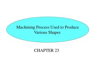
Parts Made with Machining Processes Figure 24.1 Typical parts and shapes that can be produced with the machining processes described in this chapter.
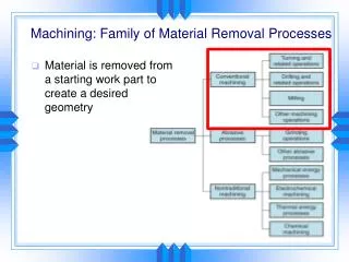
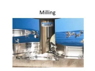
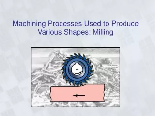
Milling and Milling MachinesMilling operations • Milling: a process in which a rotating multi-tooth cutter removes material while traveling along various axes with respect to the workpiece. • Figure 24.2: basic types of milling cutters & milling operations • In peripheral milling (also called plain milling), the axis of cutter rotation is parallel to the workpiece surface. When the cutter is longer than the width of the cut, the process is called slab milling
Milling Cutters and Milling Operations Figure 24.2 Some basic types of milling cutters and milling operations. (a) Peripheral milling. (b) Face milling. (c) End milling. (d) Ball-end mill with indexable coated-carbide inserts machining a cavity in a die block. (e) Milling a sculptured surface with an end mill, using a five-axis numerical control machine. Source: (d) Courtesy of Iscar. (e) Courtesy of The Ingersoll Milling Machine Co.
Milling Operations Figure 24.3 (a) Schematic illustration of conventional milling and climb milling. (b) lab-milling operation showing depth-of-cut, d; feed per tooth, f; chip depth-of-cut, tc; and workpiece speed, v. (c) Schematic illustration of cutter travel distance, lc, to reach full depth-of-cut.
Milling and Milling MachinesMilling operations: Slab milling • Conventional Milling (Up Milling) • Max chip thickness is at the end of the cut • Advantage: tooth engagement is not a function of workpiece surface characteristics, and contamination or scale on the surface does not affect tool life. • Cutting process is smooth • Tendency for the tool to chatter • The workpiece has a tendency to be pulled upward, necessitating proper clamping.
Milling and Milling MachinesMilling operations: Slab milling • Climb Milling (Down Milling) • Cutting starts at the surface of the workpiece. • Downward compression of cutting forces hold workpiece in place • Because of the resulting high impact forces when the teeth engage the workpiece, this operation must have a rigid setup, and backlash must be eliminated in the table feed mechanism • Not suitable for machining workpiece having surface scale.
Milling and Milling MachinesMilling operations: Slab millingMilling Parameters
Milling and Milling MachinesMilling operations: Slab millingMilling Parameters • EXAMPLE 24.1 Material-removal Rate, Power, Torque, and Cutting Time in Slab Milling • A slab-milling operation is being carried out on a 300-mm-long, 100-mm-wide annealed mild-steel block at a feed f = 0.25 mrn/tooth and a depth of cut d = 3.0 mm. The cutter is D = 50 mm in diameter, has 20 straight teeth, rotates at N = 100 rpm, and, by definition, is wider than the block to be machined, Calculate the material-removal rate, estimate the power and torque required for this operation, and calculate the cutting time. • Solution: From table 21.2 U=3 W.S/mm3
Milling and Milling MachinesMilling operations: Slab millingMilling Parameters-Example 24.2
Face-Milling Operation The cutter is mounted on a spindle whose axis of rotation is perpendicular to wp surface. Lc= D/2 Figure 24.4 Face-milling operation showing (a) action of an insert in face milling; (b) climb milling; (c) conventional milling; (d) dimensions in face milling. The width of cut, w, is not necessarily the same as the cutter radius.
Face-Milling Cutter with Indexable Inserts Figure 24.5 A face-milling cutter with indexable inserts. Source: Courtesy of Ingersoll Cutting Tool Company.
Effect of Insert Shape on Feed Marks on a Face-Milled Surface Figure 24.6 Schematic illustration of the effect of insert shape on feed marks on a face-milled surface: (a) small corner radius, (b) corner flat on insert, and (c) wiper, consisting of small radius followed by a large radius which leaves smoother feed marks. (d) Feed marks due to various insert shapes.
Face-Milling Cutter Figure 24.7 Terminology for a face-milling cutter.
Effect of Lead Angle on Undeformed Chip Thickness in Face Milling Lead angle of insert has a direct influence on undeformed chip thickness As the lead angle increases, undeformed chip thickness decreases, length of contact increases Range of lead angles = 0-45 X-sectional area of undeformed chip remains constant As lead angle decreases, there is a smaller vertical force comp (axial force) Ratio of cutter diameter, D, to width of cut should be no less than 3:2 Figure 24.8 The effect of the lead angle on the undeformed chip thickness in face milling. Note that as the lead angle increases, the chip thickness decreases, but the length of contact (i.e., chip width) increases. The edges of the insert must be sufficiently large to accommodate the contact length increase.
Position of Cutter and Insert in Face Milling Figure 24.9 (a) Relative position of the cutter and insert as it first engages the workpiece in face milling. (b) Insert positions towards the end of cut. (c) Examples of exit angles of insert, showing desirable (positive or negative angle) and undesirable (zero angle) positions. In all figures, the cutter spindle is perpendicular to the page and rotates clockwise. EXAMPLE 24.2 Material-removl Rate, Power Required, and Cutting Time in Face Milling
Milling and Milling MachinesMilling operations: End Milling • The cutter usually rotates on an axis perpendicular to workpiece • End mills are available with hemispherical ends (bull nose mills) for the production of sculptured surfaces, such on dies and molds. • End milling can produce a variety of surfaces at any depth, such as curved, stepped, and pocketed.
Ball Nose End Mills Figure 24.10 Ball nose end mills. These cutters are able to produce elaborate contours and are often used in the machining of dies and molds. (See also Fig. 24.2d.) Source: Courtesy of Dijet, Inc.
Cutters a. Straddle: more cutters are used to machine two parallel surfaces on the workpiece b. Form milling produces curved profiles using cutters that have specially shaped teeth Slotting and slitting operations are performed with circular cutters. [T-slot cutters, Figure 24.11 Cutters for (a) straddle milling, (b) form milling, (c) slotting, and (d) slitting with a milling cutter.
T-Slot Cutting and Shell Mill Figure 24.12 (a) T-slot cutting with a milling cutter. (b) A shell mill.
Machined Surface Features in Face Milling Figure 24.13 Machined surface features in face milling. See also Fig. 24.6.
Edge Defects in Face Milling Figure 24.14 Edge defects in face milling: (a) burr formation along workpiece edge, (b) breakout along workpiece edge, and (c) how it can be avoided by increasing the lead angle (see also last row in Table 24.4).
Milling and Milling MachineDesign And Operating Guidelines • Use standard milling cutters as much as possible • Chamfers should be used instead of radii • Avoid internal cavities and pockets with sharp corners • Workpiece should be sufficiently rigid to minimize any deflections resulting from clamping and cutting forces
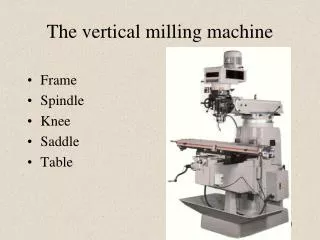
Milling and Milling MachineMilling Machines • The basic components of these machines are as follows: • Worktable: on which the workpiece is clamped using T-slots. The table moves longitudinally relative to the saddle. • Saddle: supports the table and can move in the transverse direction. • Knee: supports the saddle and gives the table vertical movement so that thedepth of cut can be adjusted and workpieces with various heights can be accommodated. • Overerarm: used on horizontal machines; it is adjustable to accommodate different arbor lengths. • Head: contains the spindle and cutter holders. In vertical machines, the head may be fixed or can be adjusted vertically, and it can be swiveled in a vertical plane on the column for cutting tapered surfaces.
Column-and-Knee Type Milling Machines Figure 24.15 Schematic illustration of (a) a horizontal-spindle column-and-knee type milling machine and (b) vertical-spindle column-and-knee type milling machine. Source: After G. Boothroyd.
Bed-type Milling Machine FIGURE 24.16 Schematic illustration of a bed-type milling machine.
CNC Vertical-Spindle Milling Machine Figure 24.16 A computer numerical-control (CNC) vertical-spindle milling machine. This machine is one of the most versatile machine tools. The original vertical-spindle milling machine used in job shops is still referred to as a “Bridgeport”, after its manufacturer in Bridgeport, Connecticut. Source: Courtesy of Bridgeport Machines Dibision, Textron Inc.
Five-Axis Profile Milling Machine Figure 24.18 Schematic illustration of a five-axis profile milling machine. Note that there are three principal linear and two angular movements of machine components.