Download
1 / 42
470 likes | 1.31k Vues
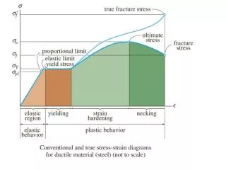
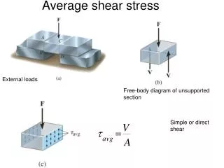
4. 剪力與斜拉力 Shear and Diagonal Tension. - Shear Failure - Shear Strength of Concrete - Shear Reinforcement by Stirrup - ACI Code Provision for Shear Reinforcement. 鋼筋混凝土樑之抗剪機制 及剪力強度預測式. 鋼筋混凝土樑之抗剪機制 剪力強度預測式. w. w l 2. R =. R. l. dx. 剪力. w. V z. v max. q max =. C+dC. C. NA.

E N D
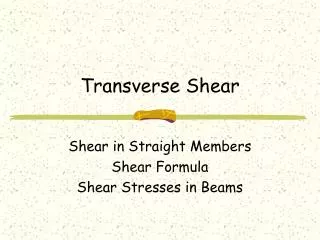
4 剪力與斜拉力Shear and Diagonal Tension - Shear Failure - Shear Strength of Concrete - Shear Reinforcement by Stirrup - ACI Code Provision for Shear Reinforcement
鋼筋混凝土樑之抗剪機制及剪力強度預測式 • 鋼筋混凝土樑之抗剪機制 • 剪力強度預測式
w w l 2 R = R l dx 剪力 w V z vmax qmax = C+dC C NA V- w dx b V z v y Ai V Ai y b I T T + dT dx q = b v v = 撓曲應力 剪應力 斷面 剪力流 樑元素 剪應力之概念
45° f2 45° f1 v f2 f1 v f v f f1 v f2 樑之主應力軌跡 The stress trajectories intersect the neutral axis at 45°. The principal tensile stresses become excessive due to cracking. 主拉應力 : 主壓應力:
A A M V A A Pure shear at neutral axis: 90o 45o 45o Web-shear crack 剪力與斜拉力Shear and Diagonal Tension Shear failure:
Potential cracks Below neutral axis: Combination of shear stress and tensile stress
Vcz C vag T Vd V 1 2 x 無腹筋RC樑之抗剪機制 • 無腹筋RC樑開裂時,其主要的抗剪機制如下所列: • 抗壓區未開裂混凝土所提供的剪力抵抗VCZ • 裂縫兩側混凝土表面的骨材鎖結作用力Vag之垂直分量Vay • 縱向鋼筋的合釘作用力Vd
Vcz C x (1) G jd (2) T Vd V 1 2 jd cot T Vd (2) V G Vay (1) Ha C Vcz Equilibrium in the Shear Span of Beam The equilibrium of the free body : V = Vcz + Vay + Vd Where : V = shear resistance in beam without web reinforcement Vcz = shear contribution of compression zone Vay = shear contribution of aggregate interlock Vd = shear contribution of dowel action M = x V = jd (T + Vd cot ) If the contribution of the dowel force is ignored (particularly in the absence of stirrups), then : M = T jd Where : M = moment resistance in beam without web reinforcement
V = = (T jd) = jd + T d(jd) dx dM dx dT dx d dx Vcz C x (1) G jd (2) T Vd V 1 2 jd cot The Principal Mechanism of Shear Resistance
V = = (T jd) = jd + T d(jd) dx dM dx dT dx d dx If the Bond between Steel and Concrete is Good In the elastic theory analysis of prismatic flexural members is assumed that the internal lever arm remain constant, then d(jd)/dx = 0, the equation of perfect “beam action” is obtained : Where : q = the bond force per unit length = shear flow
V = = (T jd) = jd + T d(jd) dx dM dx dT dx d dx d(jd) dx d(jd) dx V = T = C If the Bond between Steel and Concrete is Destroyed * The tensile force T cannot change, hence dT/dx = 0. * The external shear can be resisted only by inclined internal compression. This extreme case may be termed “arch action”. The shear resistance is expressed by :
P Line of thrust V = = (T jd) = jd + T C L d(jd) dx dM dx dT dx d jd d dx P a Slip 拱作用Arch Action in the Shear Span * Second term of the equation signifies that shear can be sustained by inclined compression in a beam. * The shaded area indicates the extent of the compressed concrete outside which cracks can form.
P P a a V = +P Shear Diagram + - V = -P M = Va Moment Diagram + 剪跨Shear Span (a = M /V ) Distance a over which the shear is constant
Variation in Shear Strength with a/d for rectangular beams Flexural moment strength Shear-compression strength Inclined cracking strength, Vc Failure moment = Va Shear-tension and shear-compression failures Deep beams Flexural failures Diagonal tension failures 0 1 2 3 4 5 6 7 a/d
撓曲裂縫及撓剪裂縫 腹剪裂縫 撓曲裂縫及撓剪裂縫 腹剪裂縫 RC樑之裂縫型態
RC樑之剪力破壞模式 腹剪開裂 撓剪開裂
拱作用 1:錨定破壞 2:承壓破壞 3:撓曲破壞 4及5:拱肋破壞 破壞之種類 深樑之剪力破壞模式
RC樑之剪力破壞模式 剪拉破壞模式 (shear-tension failure) 剪壓破壞模式 (shear-compression failure )
Span Mark (m) a/d 1 0.90 1.0 2 1.15 1.5 3 1.45 2.0 4 1.70 2.5 5 1.95 3.0 6 2.35 4.0 7/1 3.10 5.0 8/1 3.60 6.0 10/1 4.70 8.0 9/1 5.80 7.0 Crack Pattern in Several Lengths of Beam 1 2 3 4 5 6 7/1 8/1 10/1 9/1
a d a d M V d M V d Momen / Shear ratio = Momen / Shear ratio = SHEAR FAILURE MECHANISM 160 400 Theoretical flexural strength of section Mu 140 350 Shear force corresponding with the theoretical flexural capacity Vu 120 300 Observed ultimate moment 100 250 Observed ultimate shear 80 200 Moment, kNm Shear force, kN 60 150 Shear corresponding with “beam action” Flexural capacity corresponding with “beam action” in the shear span 40 100 20 50 0 0 0 1 2 3 4 5 6 7 8 0 1 2 3 4 5 6 7 8 a/d < 2.5 (Crushing / Splitting of concrete - Type 3) 2 < a/d < 3 (Shear compression failure - Type 2) 3 < a/d < 7 (Flexural tension failure - Type 1)
ACI 318規範之剪力計算強度 • 影響剪力計算強度之主要因子: • 混凝土強度 ( fc’) • 拉力鋼筋比 (w = As / bwd) • 跨深比(Shear span to depth ratio) M/Vd 精確剪力計算強度經驗公式 (U.S. customary units) (SI units) 簡化剪力計算強度經驗公式 (SI units) (U.S. customary units)
Simple formula: Shear strength with axial load: Compression: Tension:
6.0 . 5.0 . . . . . . . . . . . . . . . . . . . . . . . . . . . . . 4.0 . . . . . . . . . . . . . . . . . . . . . . . . . . . . . . . . . . . . . . . . . . . . . . . . . . . . . . . . . . . . . . . . . . . . . . . . . . v f’c v f’c v f’c . . . . 3.0 . . . . . . . . . . . . . . . . . . . . . . . . . . . . . . . . . . . . . . =1.9 + 3.5 . . . 2.0 = 2 1.0 0 0.2 0.4 0.6 0.8 1.0 1.5 2.0 = , psi 1000 wVd M f’c V bwdf’c 2500 w Vd M f’c Comparison of Simplified Expression with Experimental Result
Shear strength: from experiment vc 剪力強度Shear Strength of Rectangular Concrete Section
ACI 318規範對輕質骨材混凝土之剪力計算強度修正 • 當其平均開裂抗拉強度fct已予以規定時,fc'1/2須以fct/8替代修正之,但所用之fct/8值不得超過fc'1/2。 • 當輕質骨材混凝土之平均開裂抗拉強度fct未予規定時,fc'1/2值對全輕質骨材混凝土須乘以0.75;對於砂輕質骨材混凝土須乘以0.85;介於以上兩者間之含有部分輕質骨之輕質骨材混凝土可採內插法決定之。
Eurocode規範之剪力計算強度 式中: • k = 1.6-d1(d之單位為m) • = 1(當a/d > 2.5)或= 2.5d/a 5(當a/d < 2.5) • 為As/(bd)與0.02中之小值 • Rd= 0.25fctk0.05/c(其中:c =1.5;fctk0.05 = 0.7fctm;fctm =0.3 fc'2/3)。
Zsutty之剪力計算強度 • 當a/d < 2.5時,則上式右邊必須乘以2.5(d/a)。
25 cm 45 cm As = 18 cm2 5 cm Use simple formula: Example: Determine shear strength of the concrete section. Vu = 9 ton, Mu = 4 t-m
剪力鋼筋Shear Reinforcement Requirement No need for shear reinforcement only when: 1) Vu < f Vc/2 ; f = 0.85 for shear 2) Shallow beam (slab, footing) - d ฃ 25 cm - d ฃ 2.5 tf - d ฃ 1/2 bw
Av = 2As Shear strength provided by stirrup s s s d Number of stirrup d 腹筋所提供之剪力強度Shear Strength Provided by Stirrup
smaxฃ d/2 or 60 cm when smaxฃ d/4 or 30 cm when 含腹筋粱之剪力強度Shear Strength of RC Beam with Stirrup Vuฃ f Vn where f = 0.85 for shear Vn = Vc + Vs ; Shear strength from concrete and steel Vuฃ f (Vc+ Vs) 腹筋之最大間距Maximum Stirrup Spacing (smax)
Maximum: Minimum: 腹筋之最大與最小用量Maximum & Minimum Shear Reinforcement
剪力設計之分類Shear Design Categories (1) Vuฃ0.5 fVc No shear reinforcement (2) 0.5 fVc < VuฃfVcMin. shear reinforcement Min Vs = 3.5 bw d Max s ฃd/2 ฃ60 cm (3)fVc < Vuฃf (Vc + min Vs)same as (2)
(4) f (Vc + min Vs)< Vuฃf (Vc + 1.1 bwd) (5) f (Vc + 1.1 bwd)< Vuฃf (Vc + 2.1 bwd) Vs = Vu /f - Vc Max s ฃd/2 ฃ60 cm Vs = Vu /f - Vc Max s ฃd/4 ฃ30 cm
STEP 1 Compute Vuat critical section d from face of support w h d d L d+h/2 Critical section for shear wL/2 L/2 剪力設計之步驟Design Procedure for Shear
STEP 2 Compute shear strength Vcof concrete or STEP 3 Design shear reinforcement 0.5 Vc Vc + min Vs Where is Vn = Vu / f ?
b=40cm d=55cm Example: The simply supported beam spans 6 m, support width 40 cm, wDL= 2 t/m, wLL= 4 t/m, fy = 2,400 ksc and f’c=240 ksc. Design a vertical stirrup. wu=1.4(2)+1.7(5) = 11.3 t/m Vu = 11.3(6)/2-(.55+.2)11.3 = 25.4 ton [Vu=25.4 ton] > [fVc=0.85(18.1)=15.4 ton] f (Vc + min Vs)= 0.85(18.1+3.5ด40ด55/1,000) = 21.9 ton 21.9 ton < Vu=25.4 ton < 47.3 ton ฎ Category 4 Required Vs = Vu /f - Vc = 25.4/0.85 - 18.1 = 11.8 ton
Select stirrup RB9, Av = 2(0.636) = 1.27 cm2 Required spacing s = Av fy d / Vs = 1.27(2,400)(55)/11,800 = 14.2 cm USE 14 cm smaxฃ d/2 = 55/2 = 27.5 ฃ 60 cm USE Stirrup RB9 @ 0.14 m Ans
wu critical section d wuL/2 f Vn f Vc f Vc/2 Support Mid span Variation of Shear Capacity
Example: Redesign the beam in Ex. for stirrup at the middle half of span at x = L/4; Vu = wL/4 = 11.3(6)/4 = 16.95 ton [f Vc=15.4 t]< Vu<[fVc+min fVs=22.0 t] USE Min stirrup USE RB9: Av= 2(0.636) = 1.27 cm2 smaxฃ 55/2 = 27.5 ฃ 60 cm USE Stirrup RB9 @ 0.25 m Ans
Shear reinforcement detailing of beam in Example 0.40 RB9@0.25 RB9@0.14 RB9@0.14 1.30 1.30 3.00 6.00
Home work: Select the stirrup spacing for the beam shown below. = 280 ksc, and fy = 4,000 ksc Use DB10 stirrups. Show your results on a scaled sketch. 40 cm PL = 5 tons PD = 2 tons PL = 5 tons PD = 2 tons wL = 3 t/m wD = 2 t/m A d = 53 cm A 2.5 m 4.0 m 2.5 m Section A-A