Projections
Mapping Projections of Kentucky Bryan W. Bunch, PLS, PG Geoprocessing Specialist III Kentucky NREPC-OIS-GIS 500 Mero Street 14 th FL CPT 502-564-5174 bryan.bunch@ky.gov. Projections.


Projections
E N D
Presentation Transcript
Mapping Projections of KentuckyBryan W. Bunch, PLS, PGGeoprocessing Specialist IIIKentucky NREPC-OIS-GIS500 Mero Street 14th FL CPT502-564-5174bryan.bunch@ky.gov
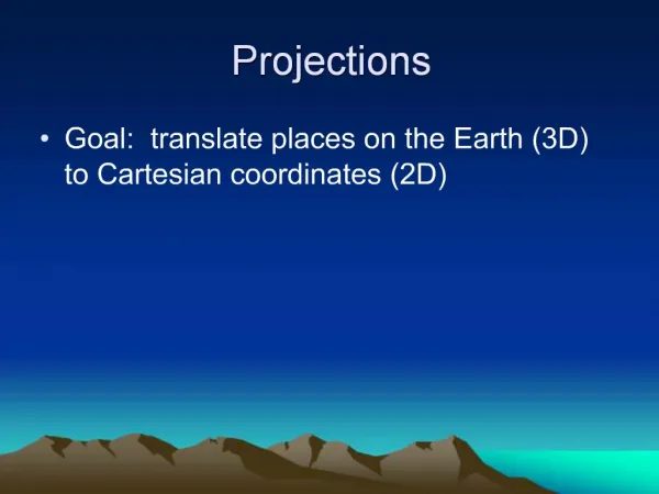
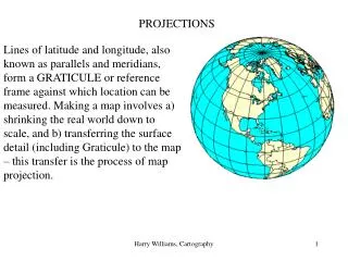
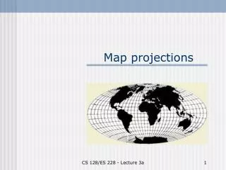
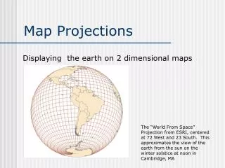
Projections • A projection is a mathematical tool that allows an N dimensional geometry to be represented within an N-1 dimensional reference frame. • A mapping projection allows a portion of spheroidal body such as the earth to be represented on a flat surface such as a sheet of paper or computer screen in a spatially consistent manner. • It is much simpler to represent and work with engineering and mapping data on a planar surface than it is a spherical surface
z P(r, ,) r y r’ P’(x, y) x Simple Projection (3-D Polar to 2-D Rectangular)
Limitations Of Mapping Projections • All mapping projections result in distortions between measurements made on the earth’s surface and their corresponding geometry on the projection plane. • While these distortions cannot be completely removed, they can be systematically constrained and quantified based on the intended purpose of the map or reference frame. • Certain characteristics of mapping projections can be preserved, but only at the expense of others.
Constraining Mapping Distortion • AREA: Equal area projections preserve areas while allowing other characteristics to be distorted. • DIRECTION: Azimuthal projections preserve relative local directions about a given point. • SHAPE: Conformal or orthomorphic projections preserve relative local angles constrained about a given point. This is accomplished by forcing the point scale factor (k) to be a function of position only and not of direction.
National Mapping Projections • The UTM and State Plane Coordinate Systems are specialized conformal mapping projections defined on geodetic datums that allow direct conversion between spherical geographic coordinates of latitude () and longitude () and their planar Cartesian counterparts of Northing (y) and Easting (x). • These projections also allow the utilization of plane surveying methods and techniques to measure small portions of the earth while constraining angular distortions in a predictable manner as opposed to the more rigorous and spatially accurate methods of geodetic surveying.
Modeling and Mapping the Earth • The topographic surface of the earth comprises a highly irregular and non-mathematical 3-dimensional figure. • Any attempt we make to define the earth’s surface in mathematical terms requires a piecemill (non-continuous) approach. • At best, any physical model of the earth inevitably requires and results in a statistical approximation. • The accuracy of the approximation is mainly dependent on the density, distribution, and accuracy of the physical observations comprising the resulting model.
The Geoid • The geoid is an equipotential gravimetric surface resulting in an irregular and non-mathematical approximation of the earth’s size and shape relative to a base of reference that best fits global mean sea level in a least squares sense. • All points on the surface of the geoid experience the same magnitude of gravimetric force. • Due to the irregular distribution of large-scale geologic features achieving varying degrees of size and density, the earth’s gravimetric field does not result in a uniform geometric figure.
Datums and Ellipsoids • A geodetic datum is a three dimensional Euclidian reference frame defined relative to an associated ellipsoid oriented to achieve a best fit statistical approximation of the geoid either in part or in whole. • The purpose of a datum is to establish a purely mathematical reference frame relative to a physical model of the earth.
North American Datum • The North American Datum (NAD) has been defined by two different ellipsoids: • The Clarke ellipsoid of 1866 which is oriented relative to the geoid to best fit the North American continent and is the basis of the North American Datum of 1927 (NAD27) • The Global Reference System of 1980 (GRS80) ellipsoid which is globally defined (geocentric to best-fit globally) and the basis of the North American Datum of 1983 (NAD83).
Datums: NAD27 and NAD83 CLARKE 1866 Ellipsoid (NAD’27) GRS80 Ellipsoid (NAD’83) Earth MassCenter Approximately236 meters GEOID
Geographic Position (Lat-Long) (variations between datums for same position)
1927 North American Datum To place on the predicted North American Datum 1983 move the projection lines 4 meters south and 6 meters west as shown by dashed corner ticks. Datum Shift: NAD27 & NAD83
Transverse Mercator Secant Cylinder (SPCS and UTM) Lambert Coaxial Secant Cone (SPCS) Common Mapping Projection Schemes
Transverse Mercator Projection SF < 1 Practical Limit of Projection (SF k0) SF > 1 Axis of Cylinder Grid Origin Intersection of Ellipsoid and Projection Cylinder (SF = 1) Central Meridian (SF = k0) Polar Axis
Kentucky ProjectionsUTM Zones 16 & 17Transverse Mercator (Secant Cylinder) UTM Zone 17 UTM Zone 16
Kentucky ProjectionsUTM Zones 16 & 17 - Projection Parameters
Lambert Conic Projection(Northern Hemisphere) North StandardParallel (SF = 1) Polar Axis Central Meridian South StandardParallel (SF = 1) Parallel ofGrid Origin(Base Parallel)
Lambert Conic Projection Typical Longitudinal Section
E1 < G1 < S1 S1 E = Distance on ellipsoidG = Distance on gridS = Distance on surface SF = Grid Scale Factor = Geodetic latitude G1 G2 < E2 < S2 S2 E1 E2 SF>1 Ellipsoid SF=1 G2 Topographic Surface(Ground) SF<1 Polar Axis North Standard Parallel Projection Grid E3 < S3 < G3 SF=1 G3 South Standard Parallel S3 SF>1 E3 Equatorial Plane Lambert Ground, Grid, and Ellipsoid FIGURE 3A
Ground to Ellipsoid Distortion • Occurs when the surface of the earth does not coincide with the surface of the ellipsoid. These distortions are compensated by elevation factors derived from surveyed or estimated elevations (orthometric heights), and observed or estimated differences between the geoid and ellipsoid (geoid height). Orthometric height is usually measured by differential leveling methods or estimated from USGS topographic maps. Geoid height can be obtained by direct GPS observation on a vertical control monument or utilizing GEOID99, a computer program and model available as a free download from the National Geodetic Survey.
TopographicSurface N > 0 h N < 0 H N R = Radius of ellipsoid in prime vertical at position latitude () H = Ground height above geoid (orthometric height) N = Geoid height (determined by GEOID99) h = Ellipsoid height Ellipsoid R Geoid N < 0 Elevation Correction Factor (EF)
Ellipsoid to Grid Distortion • Occurs where positions on the ellipsoid are transformed to fit their corresponding positions on the planar surface of the grid. This results in positions on the ellipsoid lying between the standard parallels being contracted to fit onto the projection plane, and positions lying outside the standard parallels being expanded. Distortions do not occur for positions lying on the standard parallels where both surfaces intersect and are coincidental with one another.
Scale factor: The grid scale factor (SF) is the ratio between a distance represented on the grid and its corresponding value on the ellipsoid. It is greater than one for regions lying outside the standard parallels, less than one for the region lying between the standard parallels, and exactly one for positions lying on the standards parallels. • Correcting from ground to grid: Correcting overall ground to grid distortion is achieved by computing a correction factor (CF) that is the product of the grid scale factor (SF) and the elevation factor (EF). This is multiplied by the ground distance to achieve a corresponding distance on the grid. Thus: CF = EF x SF Grid distance = ground distance x correction factor
E1 < G1 < S1 S1 E = Distance on ellipsoidG = Distance on gridS = Distance on surface SF = Grid Scale Factor = Geodetic latitude G1 G2 < E2 < S2 S2 E1 E2 SF>1 Ellipsoid SF=1 G2 Topographic Surface(Ground) SF<1 Axis of Rotation North Standard Parallel Projection Grid E3 < S3 < G3 SF=1 G3 South Standard Parallel S3 SF>1 E3 Equatorial Plane Lambert Ground, Grid, and Ellipsoid
State PlaneNorth Zone State Plane South Zone Kentucky ProjectionsNorth and South State PlaneLambert Conformal Conic (Secant Cone)
Kentucky ProjectionsNAD83 State Plane Coordinate System(Lambert Conformal Conic) Linear unit of measure for all zones is the U.S. Survey Foot (USFt) (1 USFt = 12003937 m)
Kentucky SPCS Coordinate Space Comparison 1,500,000 m 1,250,000 m NAD'83 SINGLE ZONE 1,000,000 m NORTHING 750,000 m NAD'83 SOUTH ZONE 500,000 m NAD'83 NORTH ZONE 250,000 m NAD'27 NORTH ZONE NAD'27 SOUTH ZONE 0 m 0 m 250,000 m 500,000 m 750,000 m 1,000,000 m 1,250,000 m 1,500,000 m 1,750,000 m 2,000,000 m EASTING
C o u n t y B o u n d a r y D i s t o r t i o n R a t i o s B e t t e r t h a n 1 : 2 5 , 0 0 0 1 : 1 5 , 0 0 0 - 1 : 2 5 , 0 0 0 1 : 1 0 , 0 0 0 - 1 : 1 5 , 0 0 0 1 : 7 , 5 0 0 - 1 : 1 0 , 0 0 0 1 : 5 , 0 0 0 - 1 : 7 , 5 0 0 W o r s e t h a n 1 : 5 , 0 0 0 Distribution of Ground to Grid Distortion Ratiosby Quad for Worst Case SituationsSouth Zone Projection
C o u n t y B o u n d a r y D i s t o r t i o n R a t i o s B e t t e r t h a n 1 : 2 5 , 0 0 0 1 : 1 5 , 0 0 0 - 1 : 2 5 , 0 0 0 1 : 1 0 , 0 0 0 - 1 : 1 5 , 0 0 0 1 : 7 , 5 0 0 - 1 : 1 0 , 0 0 0 1 : 5 , 0 0 0 - 1 : 7 , 5 0 0 W o r s e t h a n 1 : 5 , 0 0 0 Distribution of Ground to Grid Distortion Ratiosby Quad for Worst Case SituationsSingle Zone Projection
National Geodetic Survey, Retrieval Date = AUGUST 12, 2002 GZ0132 *********************************************************************** GZ0132 CBN - This is a Cooperative Base Network Control Station. GZ0132 DESIGNATION - I75 L 83 GZ0132 PID - GZ0132 GZ0132 STATE/COUNTY- KY/MADISON GZ0132 USGS QUAD - RICHMOND NORTH (1993) GZ0132 GZ0132 *CURRENT SURVEY CONTROL GZ0132 ___________________________________________________________________ GZ0132* NAD 83(1993)- 37 51 34.68569(N) 084 19 59.19617(W) ADJUSTED GZ0132* NAVD 88 - 286.293 (meters) 939.28 (feet) ADJUSTED GZ0132 ___________________________________________________________________ GZ0132 X - 497,891.230 (meters) COMP GZ0132 Y - -5,017,564.276 (meters) COMP GZ0132 Z - 3,893,310.905 (meters) COMP GZ0132 LAPLACE CORR- 0.42 (seconds) DEFLEC99 GZ0132 ELLIP HEIGHT- 253.79 (meters) GPS OBS GZ0132 GEOID HEIGHT- -32.51 (meters) GEOID99 GZ0132 DYNAMIC HT - 286.087 (meters) 938.60 (feet) COMP GZ0132 MODELED GRAV- 979,903.0 (mgal) NAVD 88 GZ0132 GZ0132 HORZ ORDER - B GZ0132 VERT ORDER - SECOND CLASS 0 GZ0132 ELLP ORDER - FOURTH CLASS I . . . GZ0132; North East Units Scale Converg. GZ0132;SPC KY1Z - 1,170,338.983 1,624,669.125 MT 0.99990498 +0 52 11.7 GZ0132;SPC KY1Z - 3,839,687.15 5,330,268.62 sFT 0.99990498 +0 52 11.7 GZ0132;SPC KY S - 670,320.267 624,679.514 MT 0.99998738 +0 51 33.4 GZ0132;SPC KY S - 2,199,209.08 2,049,469.37 sFT 0.99998738 +0 51 33.4 GZ0132;SPC KY N - 39,921.624 492,686.218 MT 1.00001792 -0 03 06.1 GZ0132;SPC KY N - 130,976.19 1,616,421.37 sFT 1.00001792 -0 03 06.1 GZ0132;UTM 16 - 4,193,593.825 734,612.496 MT 1.00027800 +1 38 15.0 KY1Z = Kentucky Single Zone http://ngs.state.ky.us