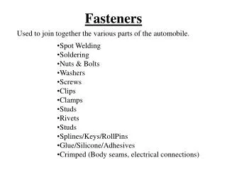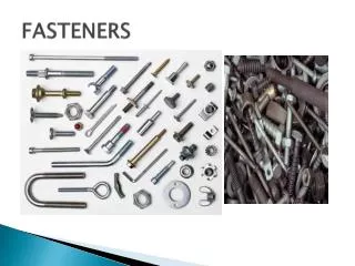
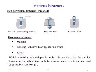
Various Fasteners
Permanent fasteners. Welding. Bonding (adhesive, brazing, and soldering). Rivets. Various Fasteners. Non-permanent fasteners (threaded). Machine screws (cap screws). Bolt and Nut. Stud and Nut.

Various Fasteners
E N D
Presentation Transcript
Permanent fasteners • Welding • Bonding (adhesive, brazing, and soldering) • Rivets Various Fasteners Non-permanent fasteners (threaded) Machine screws (cap screws) Bolt and Nut Stud and Nut Which method to select depends on the joint material, the force to be transmitted, whether detachable fastener is desired, fastener cost, cost of assembly, and weight. SJSU
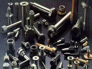
Tamper resistant screw heads Some common screw and bolt head type Threaded Fasteners SJSU
The American National (Unified, UN) standard thread UNC (Coarse thread) – has fewest threads per inch than other series, good for frequent assembly and disassembly, use where vibration is not a problem, reduces the likelihood of cross-threading. Thread Standards and Terminology SJSU
Metric standards M12 x 1.75 Pitch, p in mm Major diameter, mm Thread Standards and Terminology UNF (Fine thread) – has more threads per inch than UNC, use where higher bolt strength is needed, has less tendency to loosen under vibration (smaller lead angle). UNEF (Extra Fine thread) – has more threads than other series, use for precision applications or for thin-wall applications. UNRF (Fine thread) – has rounded root contour to reduce stress concentration and enhance resistance to fatigue failure. Thread Classes – specifies ranges of dimensional tolerance and allowance. Class 1A, 2A, and 3A apply to external threads and 1B, 2B, and 3B apply to internal threads. The higher the class the smaller the tolerance. Thread series Fit class 1/2 - 20UNF – 2A or (1/2 – UNF) Major diameter Threads per inch SJSU
Use tensile stress area, At, for all stress calculations The mean of the pitch diameter and the minor diameter is used to calculate the tensile stress area. Basic dimensions of Unified threads SJSU
Torsion Root diameter τ= 16 T / πdr3 Bearing stress σt=4P / [π (d2 – dr2)] (h/p) Number of threads in contact Stripping stress τ (screw)= P / πdr (.8h) , τ (nut)= P / πd (.88h) Stresses in Threads Axial load Tensile stress area σt=P / At h Use a safety factor of 2 with these equations SJSU
Minimum tapped-hole engagement A longer thread engagement is needed if a screw is threaded into a tapped (blind) hole. Same material (bolt and member) L(tapped hole length) ≥ d Steel bolt in cast iron, bronze, or brass L(tapped hole length) ≥ 1.5d Steel bolt in aluminum L(tapped hole length) ≥ 2d Minimum Nut Height If the nut is long enough, the load require to strip the threads will be larger than the load needed to fail the screw in tension. For unified and metric threads, a nut height of at least 0.5d will have a strip strength higher than the screw’s tensile strength. SJSU
member carries all of the load Bolted Joints in Tension – Effect of Stiffness Bolt carries all of the load SJSU
If there is no separation then, the deflection of the bolt and member has to be the same Bolt force No separation Stiffness ratio Bolt Force SJSU
Springs in series Bolt stiffness, or use Bolt Stiffness The portion of the bolt in the clamping zone (grip) consists of unthreaded and threaded sections. SJSU
If the members in the joint are made of the same material and have the same thickness then, and using Member stiffness Member Stiffness – Shigley method Stiffness of a joint made of different members Distribution of the pressure through the member resembles a cone. SJSU
Member Stiffness – Juvinal method The stiffness of clamped members km = AcE / grip length where Ac is the effective area of clamped members SJSU
Confined gasket Confined O-ring Unconfined gasket should be considered as a member. If the gasket is made of a soft material (low E), the gasket stiffness will dominate the total member stiffness, km = kg = AgEg / tg Gasket material Copper E = 17.5x10⁶ psi Plain rubber E = 1000 psi Teflon E = 35x103 psi Cork E = 12.5x10³ psi Member Stiffness Gasketed joints Unconfined gasket Confined seals allow the hard faces of the members to contact, joint behaves as unsealed one, same member stiffness km as before. SJSU
Initial Tension (preload) Recommendation for both static and fatigue loading Tensile stress area Fi = Ki At Sp Proof strength Constant, 0.75 to 0.9 Bolt should not be reused If tightened to 90% of the proof load (Fp = At Sp), yielding may have occurred. For static loads and permanent connection, tighten to 90% of the proof load. For fatigue loading and non-permanent connections (reused fastener) tighten to 75% of the poof load. SJSU
Why High Preload? • External loads (tensile) tend to separate members, bolt force cannot increase much unless the members separate, the higher the preload the less likely the members are to separate. • For external loads tending to shear the bolt, the higher the preload the greater the friction force resisting the relative motion in shear. • Higher preload reduces the dynamic load on the bolt because the effective area of the clamped members is larger. • Higher preload results in maximum protection against overloads, which can cause joint separation, and provides protection against thread loosening. SJSU
T = 0.2 Fi d Bolt Tightening - Torque Tightening torque related to preload and bolt diameter. The constant value, .2, remains approximately the same regardless of the bolt size. For critical applications a torque wrench should be used to apply the proper preload. SJSU
Bolt stress Bolt stress has to be less than the proof strength Safety factor for static load Joint separation , Safety factor against separation Design of Bolted Joints in Tension under Static loads Bolt force SJSU
Select bolt grade ( grade 5 and 8 are common) Sp , Sy , Su , Se • Use preload,Fi = 0.9At Sp • Calculate torque,T = 0.2Fi d Design of Bolted Joints in Tension under Static loads Design steps Static load with no seal and considering separation as the worst case, bolt carries all of the external load, stiffness not considered. Fm = 0, Fb = P • Determine the maximum load per bolt, select a safety factor (n = 2) and calculate the design load. P (design) = nP • Calculate the required tensile stress area. Sp = P (design) / At • Select bolt size, d, from the table SJSU
Select bolt grade ( grade 5 and 8 are common) Sp , Sy , Su , Se • Solve for safety factor n, check against the value selected in step 3, iterate if until the desired safety factor is reached. Design of Bolted Joints in Tension under Static loads Design steps Considering stiffness (joint not separating) • Determine the maximum load per bolt, P. • Select a safety factor, n = 2. • Assume bolt diameter, d. • Look up At , and calculate bolt and member stiffness to find C. • Determine the preload,Fi = 0.9At Sp • Specify torque,T = 0.2Fi d SJSU
Design Example A pillow block is attached by two machine screw. You are asked to select appropriate screws and specify the tightening torque. • Select a relatively inexpensive bolt grade, 5.8 with proof strength of 380 MPa • Determine the maximum load per bolt, select a safety factor (n = 2) and calculate the design load. P (design) = 2 (9000/2) = 9000 N • Calculate the required tensile stress area. At = P (design) / Sp = 23.68mm2 • Select bolt size, d, from the table, d = 7 mm, (At = 28.9 mm2) • Use preload,Fi = 0.9At Sp = 0.9 (28.9)(380) = 9883.8 N • Calculate torque,T = 0.2Fi d = .2 (9883.8)(7) = 13.84 N-m SJSU
(Fbolt)max = maximum load applied to the bolt = C Pmax + Fi (Fbolt)min = minimum load applied to the bolt = C Pmin + Fi Fa = alternating load = (Fmax – Fmin)/2 σa = alternating stress = Fa /At Fm = mean load = (Fmax + Fmin)/2 σm = mean stress = Fa /At Use Goodman line as design criteria σa σm 1 = + nf Se Sut Endurance limit Fatigue safety factor Ultimate strength Design of Bolted Joints in Tension under Fatigue loading Pmax = maximum applied load to the joint Pmin = minimum applied load to the joint SJSU
Su(Pmax – Pmin) + Se(Pmax + Pmin) + 2(SeFi )/C At = nf 2(SeSu )/C Endurance Strength, Se Suggested values for endurance limit for common bolts with rolled threads. For cut threads use Kf= 3.8 for grade 4 and higher. multiply the alternating component of stress by Kf. Design of Bolted Joints in Tension under Fatigue loading Design equation Common case, Pmin = 0, so (Fbolt)min = Fmin = Fi SJSU
Goodman σa σm 1 nf = safety factor guarding against fatigue failure. σa σm 2 nf = + 2 nf nf Se Sut 1 = + Se Sp ASME-elliptic Yielding Sp ny = ny = safety factor guarding against yielding. σm σa + Design of Bolted Joints in Tension under Fatigue loading Fatigue failure criteria Sp= proof strength Sut= ultimate strength in tension , Se= endurance limit SJSU
Select bolt grade ( grade 5 and 8 are common) Sp, Sy, Su, Se Design of Bolted Joints in Tension under Fatigue loading Design steps • Select number of bolts. If circular pattern, use the restriction 3 ≤ (π Db)/N d ≤ 6 to allow access to bolt head for tightening. Db is bolt pattern diameter, d is bolt diameter and N is the number of bolts. • Determine the maximum and minimum applied load per bolt, Pmax and Pmin. • Choose a safety factor, nf = 1.5 to 2.5 • Choose a bolt diameter, d, look the tensile stress area, At and calculate the stiffness ratio C. • Decide on preload Fi. Use .6SpAt≤ Fi≤ .9SpAt as guideline, (Fi = .75 SpAt is common). Unless specified otherwise by seal manufacturer. • Use the design equation and calculate the safety factor, nf , iterate until the calculated safety factor matches the chosen one in step 4. SJSU
Select 14 grade 9.8 bolt. Sp =650, Sy= 720, Su= 900, andSe=140 MPa • Determine the maximum and minimum applied load per bolt, Pmax and Pmin. Pmax = (pressure)(Area) / N= (2.0)(π Di2/4) = [(2)(π)(250)2/4] / 14 = 7013 N Pmin = 0 Design Example – Fatigue Loading Consider a cast iron cylinder with aluminum cover plate with internal gage pressure that fluctuates between 0 and 2.0 MPa. Both members 10 mm thick. Design the bolted joint.Specify the bolt grade, number of bolts and bolt diameter for infinite life. • Choose a safety factor, nf = 1.5 • Choose a bolt diameter, d = 12 mm, look up At = 84.3 mm2 • Check bolt spacing, 3 ≤ (π Db)/N d ≤ 6 , 3 ≤ (π 350)/12x14 = 6.5 ≤ 6 (okay) SJSU
kb = 1.17x10⁶ N / mm Member stiffness, 1/km = 1/kAl + 1/kcast k = AE / grip length kAl = AcEAl / g = 333.2x70,000/10 =2.332x10⁶ kcast = AcEcast / g = 333.2x100,000/10 =3.332x10⁶ km = 1.37x10⁶N / mm Stiffness ratio, C = kb / (kb + km) = .46 Design Example – Fatigue Loading • Calculate stiffness ratio, C. Bolt stiffness, kb = AboltE / grip length = πd2E / 4g = π122x207x103 / 4x20 Ac = d2 + .68dg + .065g2 = 122 + .68x12x20 +.065x202 = 333.2 SJSU
Calculate safety factor Su(Pmax – Pmin) + Se(Pmax + Pmin) + 2(SeFi )/C At = nf 2(SeSu )/C • Select grade 10.9 bolt, Sp = 830, Sy = 940, Su = 1040, and Se = 162 MPa Fi = .75 SpAt = .75 x 830 x 84.3 = 52,477 N nf = 1.36 < 1.5, use more bolts, select 24 bolts Check bolt spacing, 3 ≤ (π 350)/12x24 = 3.8 ≤ 6 (okay) Design Example – Fatigue Loading • Select preload Fi = .75 SpAt = .75 x 650 x 84.3 = 41,100 N nf = 1.1 < 1.5, select larger diameter or higher strength bolt SJSU
Specification Bolt diameter 12 mm # of bolts 24 Bolt grade 10.9 metric Design Example – Fatigue Loading Determine the maximum applied load per bolt, Pmax. Pmax = (pressure)(Area) / N= (2.0)(π Di2/4) = [(2)(π)(250)2/4] / 24 = 4090 N nf = 1.47 ≈ 1.5 SJSU
Primary shear – same for all bolts F‘=V / # of bolts Secondary shear – for the nth bolt Mrn Fn״= rA2+ rB2 + rC2 + ….. Bolted Joints in Shear SJSU
FC = FD = 14.8 kN FA = FB = 21.0 kN What grade of bolt should be used? Bolted Joints in Shear V = 16 kN , M = 16(425) = 6800 N-m τ=F / As=21/144 = 146 MPa Use grade 4.8, Ssy = 155 MPa SJSU
Bolted Joints in Shear Consider a bracket attached to the wall by two bolts as shown. • Assume shear is carried by friction • Neglect friction and assume shear is carried by the bolts SJSU