Download
1 / 51
530 likes | 1.1k Vues
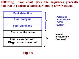
Fault Detection, Consequence Prevention, and Control of Defeat. “To find fault is easy; to do better may be difficult” -- Plutarch . Harry J. Toups LSU Department of Chemical Engineering with significant material from SACHE 2003 Workshop presentation by Max Hohenberger (ExxonMobil).

E N D
Fault Detection, Consequence Prevention, and Control of Defeat “To find fault is easy; to do better may be difficult” -- Plutarch Harry J. Toups LSU Department of Chemical Engineering with significant material from SACHE 2003 Workshop presentation by Max Hohenberger (ExxonMobil)
Fault Detection /Consequence Prevention • Fault – The partial or total failure of a device. • Detection – The ability to recognize the functional ability of a device. • Consequence – Something produced by a cause or following from a set of conditions. • Prevention – The ability to overcome an undesirable outcome from a given set of conditions or circumstances.
Why are We Interested? • We want Fault Tolerance • Fault Tolerance – The extent to which a process or system will continue to operate at a defined performance level even though one or more of its components are malfunctioning. • Why? • Safety • Reliability
Fault Recognition • Whether it’s … • the temperature input to a reactor trip system • the elevator controls on a Boeing 747, or • the safety shutdown for a high pressure boiler, • You can’t address what you don’t know is broken.
Fault Detection – Designed In • Deviation Alarm • Value of the sensor is automatically compared with redundant sensors for validity checking • If the difference exceeds a preset tolerance, an alarm is triggered. • Diagnostics • Real-time artificial intelligence that compares current status bits for conformance with pre-defined rules. • Alarms are generated whenever the rules are violated.
Failure Modes and Design • Fail-Action (Fail-Safe) – If a fault occurs or the energy source is lost, the protective system initiates the protective action. Also known as ade-energize-to-trip design. • Fail-No-Action (Fail-to-Danger) – If a fault occurs or the energy source is lost, the protective system will not be able to take the desired protective action. Also known as anenergize-to-trip design.
Fault Detection – Designed In • Simulated process demand conditions are imposed on the system to verify functionality & find any hidden faults. • Provisions are made in the design to facilitate on-line testing as much as possible. • If a fault is detected, repairs are made ASAP to restore full protective functionality. • In cases where repairs cannot be readily accomplished, alternate protection is placed in service or operations are taken to a stable, safe state until the repairs can be made. • Testing CONTROL of DEFEAT
Fault Tolerance – Designed In • Redundancy – The ability to tolerate faults is enhanced by the use of multiple components. This includes such things as redundant sensors/logic solvers/output devices. • Multiple Sensors – Multiple input devices which can be used for voting/validity checking/median value selection. • Independent Technologies – Use of different sensor/ output types to avoid common cause failure modes.
Fault Tolerance – Designed In • Triple Modular Redundant (TMR) – Three independent Programmable Logic Controllers (PLC) used in a (2-out-of-3) voting arrangement such that the loss of any single processor (or any component) will not result in loss of the protective function, nor in an unnecessary trip • Redundant Outputs – Two or more final elements, each independently capable of providing the desired protective function, used in tandem with each other.
Fault Tolerance – Standards • Safety Instrument System (SIS) – The instrumentation or controls that are responsible for bringing a process to a safe state in the event of a failure. • Safety Integrity Level (SIL) – A statistical representation of the availability of a Safety Instrument System (SIS) at the time of a process demand.
Safety Integrity Level – SIL • Average probability-to-fail-on-demand (PFDavg) – A statistical measurement of how likely it is that a process, system, or device will be operating and ready to serve the function for which it is intended. • Meets SIL 3 specification (less than 0.001)
Fault Tolerance – TMR System • NO single point of failure • Very high Safety Integrity Level (SIL) • Comprehensive diagnostics and online repair • MTTF can exceed 1000 years!
Fault Tolerance – Designed In • Fault tolerant designs to avoid common cause failures for multiple I/O and logic solvers: • Use of separate taps for multiple sensors • Use of multiple power sources • Distribution of I/O to prevent single card failure from impacting all I/O related to a single function • Use of redundant/distributed wiring paths • Environmental controls for moisture, lightning, etc • Rigorous factory acceptance and site use testing.
Fault Tolerance – TMR System Typical Architecture Model
Fault Tolerance • Simplex System (single input/single logic solver/ single output) – A single fault results in the loss of protection and/or unnecessary shutdown. • Redundant System (multiple inputs/multiple processors/multiple outputs) – A single fault will result in an immediate alarm but will not result in loss of protection nor in an unnecessary shutdown.
Fault Tolerance • Fault Tolerant Designs/Methods: • Use of analog transmitters versus switches • Use of sealed capillary transmitters versus wet-leg sensors • Positive feedback on output circuits • Slight time delay on most trip inputs • Fireproofing on critical actuators/circuits to give increased operating time before failure in the event of a fire
Typical TMR Applications • Emergency Shutdown Systems • Burner Management Systems • Fire and Gas Systems • Critical Turbomachinery Control • Railway Switching • Semiconductor Life Safety Systems • Nuclear Safety Systems
Fault Tolerance /Consequence Prevention • Interactive training of operations/maintenance personnel on protective system operation • Simulated emergency training, both initial and refresher. • Evergreen review of protective system adequacy based on unit changes, performance history, unit manning, etc. • Design verification through both qualitative and quantitative review exercises.
Fault Response • Covert Faults – Hidden or non-self revealing faults. • Since there is no fault detection, there is no fault response. • This could result in a fail-to-danger situation. • Such a fault would normally only be found during periodic manual testing w/o smart diagnostics.
Fault Response • Overt Faults/Simplex system – Obvious or self-revealing faults • Overt faults in simplex systems normally result in an unnecessary shutdown. • The majority of protective system designs are fail-safe, so the process goes to the safe state upon a single overt fault condition.
Fault Response • Overt Faults/Redundant Systems • Normal result of a single overt fault is an alarm with a degradation from a 2-o-o-3 voting system to a 1-o-o-2 voting system • Any subsequent fault would result in the designed protective system action • The protective system may take additional precautionary action to minimize the consequences of any further faults as shown on the following slide.
Fault Response • Overt Faults/Redundant Systems: (continued) • Upon fault detection, the system may take one of a number of options, depending on fault and potential consequence: • Continue at full production rates with alarm only • Gracefully decrease process to lower rates • Implement a total process shutdown. • Upon fault detection, a COD would be implemented, alternate protection put in place, and repair would be implemented ASAP to restore functionality and reliability.
Next Level of Improvements • Improved alarm suppression to prevent the major alarm flood associated with a rapidly degrading process situation: • Safety Critical alarms always remain active • Operations Critical alarms temporarily suppressed by conscious operator action. • Operations Important alarms automatically suppressed until sufficient process stability returns.
Next Level of Improvements • Improved diagnostic capabilities for sensors, logic solvers, and final elements • This includes process condition sensing, such as for lead line fouling, icing, valve sticking, etc. • Additional / advanced use of artificial intelligence would be one possibility for further enhancements in this area.
Next Level of Improvements • Improved on-line, self-testing capability of sensors and final elements: • Testing needs to be non-disruptive to process but sufficient to be representative of device capability • Automatically initiated (time or condition based) and self-documenting
Next Level of Improvements • Guidelines/standards around the use of spread spectrum radio equipment for critical system applications • Remote applications • Eliminate ground loop / ground plane issues • Immune to interference • Natural path to redundancy
Next Level of Improvements Where are faults occurring in protective systems? Final Element 55% Sensor 40% Logic Solver 5%
Next Level of Improvements Where is the lion’s share of research in reliability/diagnostics/base innovations being seen? Final Element 15% Sensor 25% Logic Solver 60%
Definition of a Critical Device* • A Critical Device is the last line of defense against, or would be used to mitigate the consequences of, a significant undesirable process incident • Consequence include the following: • An uncontrolled, major loss of containment of a toxic or highly flammable material • Likely result in severe personal injuries, illness or death • Present immediate risk to plant personnel, the community, or the environment * Critical means a Safety/Health/Environ. Critical
Examples of Critical Devices • Pressure relief valves in safety service • Emergency Shutdown Systems and associated measurement and action components
Control of Defeat (COD) • When a S/H/E Critical Device is taken out of on-line service for any reason, defeating its ability to perform its intended function, a formal Control of Defeat (COD) must be implemented to ensure that: • Suitable alternate protection is provided • All potentially impacted parties are fully informed for the entire duration of the Defeat • The device is properly returned to service following the outage
With Proper COD Usage Same Exact Unit Without Proper Use of COD Why Properly Use Control of Defeat?
Prerequisites for Defeating • A Critical Device should only be Defeated if it is necessary to prevent a greater risk or to perform a Test/PM/Repair of the Device. • A Critical Device should not be Defeated if: • Suitable alternate protection cannot be provided • The unit is in an upset condition (current condition is not stable or outside of defined normal operating window; i.e, starting up, shutting down, running a controlled test, etc.).
COD Documentation • One of the benefits of the full, complete use of COD documentation is that it serves as a checklist to help people think through: • Potential safety implications of taking a Critical Device out of full, on-line service • The viability/manageability of the planned alternate protection • The importance of returning the Critical Device properly to on-line service in a timely fashion
Initial Defeat • A Defeat during the first shift out-of-service is called the Initial Defeat • It must be approved by the Operations 1st-Line Supervisor (FLS) and posted in a prominent, known location • It must be communicated to the 2nd-Line Supervisor (SLS)
Extended Defeat • If a Critical Device Defeat is in place longer than the first shift, the FLS must approve Extended Defeat and inform the affected personnel • Each/every succeeding oncoming shift FLS must inform their team of the Defeat • If the Defeat lasts more than 7 days, the SLS must approve Long-Term Defeat and notify upper management
Long-Term Defeat • If the Defeat of a Critical Device lasts longer than 7 days, a Long-Term Defeat Plan must implemented. This plan must include: • The reason for the extension • Any additional precautions • Any additional communications needs • The projected length of the extension
COD Documentation • All COD’s, regardless of length, require full and proper completion of the following: • Date/Time Defeated • Device/System Defeated • Reason for the Defeat • Defeat Plan • Notification of all affected parties • Approval by the appropriate level • Notification of the appropriate higher level • Proper lineup/return to service sign-off • COD closeout sign-off
COD Compliance Issues • Omission of or improper completion of one/more of the requirements listed previously; e.g., inadequate alternate protection or failure to sign/initial • Failure to use a Control of Defeat when taking a Critical Device out of full, on-line service for Testing/PM/Repair/etc. • Failure to properly return a Critical Device to on-line service
Alternate Protection Plan • How a process demand will be mitigated while a Critical Device is Defeated • The alternate protection needs to be written in sufficient detail so that operations backfill can adequately execute the plan • In many cases, the initiator will not be available for consultation as her/his shift is finished
Is a COD Needed for This Work? • A low level alarm is going to be tested by actually lowering the vessel level. NO– The level device is always available for an actual process demand.
Is a COD Needed for This Work? • A low level alarm is going to be tested by blocking the instrument line to the vessel and bleeding the line to simulated a low level YES– While the instrument is blocked out from the vessel, the level alarm is not available for an actual process demand, therefore alternate protection is needed
Is a COD Needed for This Work? • It’s only going to take 2 minutes to do the test, and it takes longer than that to fill out the COD. A caution note on a procedure is sufficient to manage the risk. YES– Even though the intended outage is only 2 minutes, the testing could be interrupted by a unit upset, the weather, etc., alternate protection may be inadequate, it’s more likely that the device may not be returned to service
Is a COD Needed for This Work? • The assistant operator is working with the instrument tech, and they are both in radio contact with the Operations Center YES– While radio contact might be an integral part of the alternate protection, a COD ensures that all other potentially impacted parties are informed, alternate protection is used, and the Critical Device is returned to on-line service when the activity is completed
Is a COD Needed for This Work? • A Critical Device is found broken and needs to be repaired. The device will be out of service until repairs are completed YES– Regardless of how long the repairs will take (even if during the same shift as discovered), a COD should be initiated once a Critical Device is discovered to be incapable of providing the required protection. It must stay in force until the Critical Device is returned to full, on-line service
Real Life COD Failure Example • “The (collision warning) system was not working at the time …” – Roger Gaberelle, a spokesman for Swiss air traffic controllers. • “Swiss air traffic controllers said on Wednesday an automatic collision warning system had been switched off for maintenance when two jets crashed into each other over Germany, killing 71 people.” – Reuters (July 2002)