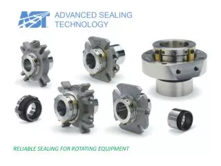
Rotating Equipment
Rotating Equipment. PUMPS. Rotating Equipment. HIGH PRESSURE. Rotating Shaft. LOW PRESSURE. It’s all in the ‘Seal’. ROTATING EQUIPMENT. PUMPS COMPRESSORS AGITATORS FANS / BLOWERS TURBINES VACUUM PUMPS VALVES. Type of Seals. Increasing Leakage Rate. Stuffing Cheapest

Rotating Equipment
E N D
Presentation Transcript
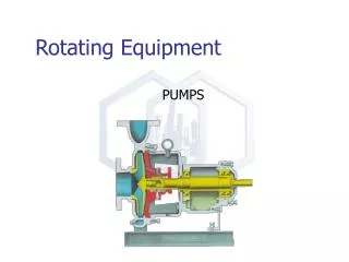
Rotating Equipment PUMPS
Rotating Equipment HIGH PRESSURE Rotating Shaft LOW PRESSURE It’s all in the ‘Seal’
ROTATING EQUIPMENT • PUMPS • COMPRESSORS • AGITATORS • FANS / BLOWERS • TURBINES • VACUUM PUMPS • VALVES
Type of Seals Increasing Leakage Rate • Stuffing • Cheapest • Leaks Continuously for cooling • Mechanical Seal • More expensive • Trace amounts of leakage for cooling • Double Mechanical Seal • Sealess (Magnet Coupled, Canned) • Most Expensive Increasing Cost
Seal Location ‘SEAL’
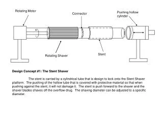
ROTATING EQUIPMENT “STUFFING BOX”
Rotating Equipment • Packing Material
Rotating Equipment • Valve Packing
ROTATING EQUIPMENT • SINGLE MECHANICAL SEAL - Pusher Type Pump Housing Seal Face Spring High Press Fluid Shaft
ROTATING EQUIPMENT • John Crane EZ-1 Single Mechanical Seal www.johncrane.com
ROTATING EQUIPMENT • Single Mechanical - Bellows Mechanical Seal
ROTATING EQUIPMENT • Bellows Mechanical Seal
Rotating Equipment • Double Mechanical Seal Outboard Seal Face Barrier Fluid Inboard Seal Face Inboard Seal Outboard Seal
Rotating Equipment • Double Mechanical Seal - Barrier Fluid
Rotating Equipment • Sealless Pumps - Magnetic Drive
Rotating Equipment • Sealless Pumps - Canned Motor
Rotating Equipment • Sealless Pumps - Canned Motor Pump
Rotating Equipment • Pumps - Air Operated
Rotating Equipment • Rotary Gear Pump High viscosity fluids ( > 10 cP)
Rotating Equipment • Positive Displacement - Diaphragm Pump Low viscosity fluids ( < 10 cP)
Rotating Equipment • Positive Displacement - Diaphragm
Rotating Equipment • Agitators
Rotating Equipment • Agitators
Rotating Equipment • Agitators
Rotating Equipment • Agitators
Pump Selection • Single Stage Centrifugal Pumps for 0.057-18.9 m3/min, 152 m maximum head • Rotary Pumps for 0.00378-18.9 m3/min, 15,200 m maximum head, • Reciprocating Pumps for 0.0378-37.8 m3/min, 300 km maximum head,
Common Equations (HP)
Pump Sizing • 5 Easy Steps • Draw a Diagram • Determine the flow • Determine the inlet pressure • Determine the discharge pressure • Calculate shaft power
Min Flow Bypass Line and orifice plate Pump Sizing - Step 1 • 1.Draw A Diagram ! - based on P&ID Destination 1 PT PIC 5 bar(g) Destination 2 9 bar(g) Source Pressure = 1.5 bar(g) Liquid Level Pump Discharge Pressure Pump Suction Static Head Pump Suction Pressure
Pump Sizing - Step 2 • 2.Determine the Flow Rate • Take Simulation Flow add 20% • If there’s a min flow bypass- it’s flow is 15% of the rated flow • Simul = 100 gal/min • Rated flow = 100 gpm * 1.20 • Rated flow = 120 gal/min • If Min Flow Bypass 100 * 1.20 / (1-0.15) • Rated flow = 141 gal/min
Pump Sizing - Step 3 • 3. Determine Pump Inlet Pressure • Use Pressure from Simulation • Assume elevation changes offset piping pressure drops
Pump Sizing - Step 4 • 4. Determine Discharge Pressure • Look Downstream of the pump for a place in the process where the pressure is controlled (or P is atmospheric or P is set by vapour pressure of fluid in tank) PIC LT PT LIC PV LV
Pump Sizing - Step 4 • 4. Determine Discharge Pressure • Work Backwards from Downstream Pressure • Work your way back to pump adding/subtracting • add DP due to frictional loss (piping) • add OR subtract DP due elevation changes • add DP due to control valves • add DP due to equipment (exch, packed bed reactors, etc.)
Pump Sizing - Step 4 • Assume (first pass) that Control Valves have 10 psi differential. • If there’s more than one control valve in parallel go back later and determine which one has the 10 psi and which one(s) has more. • Do DP of min flow bypass orifice last.
Pump Sizing - Step 4 • Determine the Control Valve DP 1 bar 0.5 bar
Pump Sizing - Step 4 • Determine the Control Valve DP • Control Valve Sizing • CV vs % Opening Characteristic
Pump Sizing - Step 4 • CV vs % Opening Characteristic
Pump Sizing - Step 4 • Piping DP = 15 psi at rated flow • Flow Elements (FE’s) = 3 psi • Heat Exchangers = 10 psi • Filters - there are none • Packed Beds - hmmm 25 psi in liq service • could use Ergun Equation (See Perry’s) to calc
Pump Sizing - Step 5 • Determine Pump Differential Pressure • Subtract Inlet Press from Discharge Press • (note error in equipment list spreadsheet) • Assume efficiency • Calc Pump Shaft Power
Goulds Pump Sizing • 3600 or 1800 RPM • Start with Model 3196 (Standard Chemical Service) • Look for the pump with the highest efficiency http://www.gouldspumps.com/gp_hss.ihtml
PIC PT CWS CWR PV FV FIC RO FT PI PI HS I M HS
Flow: 4372 kg/hr (simulation), SG = 0.75 Diagram! 23/0.6*1.1= 43 trays height to reflux nozzle= 43*2ft+6 ft = 90 ft Find the pump type, hydraulic horsepower, and the Brake HP Workshop 275 kPa FT 275 kPa
Questions • NPSH • compression ratio • driver types
NPSHa = available NPSHr = required NPSHa vs NPSHr