Download
1 / 76
760 likes | 867 Vues
Explore advancements in ultra-high-speed image sensors & innovative pixel architecture towards 1Giga-frames-per-second imaging. Review of technologies, example illustrations, and insights on achieving ultimate high-speed imaging.

E N D
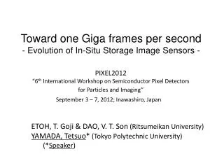
Toward one Giga frames per second- Evolution of In-Situ Storage Image Sensors - PIXEL2012 “6th International Workshop on Semiconductor Pixel Detectors for Particles and Imaging” September 3 – 7, 2012; Inawashiro, Japan ETOH, T. Goji & DAO, V. T. Son (Ritsumeikan University) YAMADA, Tetsuo* (Tokyo Polytechnic University) (*Speaker)
OUTLINE • Review of Ultra High Speed Image Sensors • Using In-Situ CCD Memory • ・ Advanced BSI Technologies • ・ Example of High Speed Imaging • 2.New Pixel Architecture toward 1G-fps ・ Design Concept • ・ Pattern Layout and Driving Sequence • 3.Consideration for Possibility of 1Gfps Imaging ・Frame Rate Limitation・ Simulation Results • 4. Summary
In-pixel signal accumulation by coiled loopCCDs being designed In-pixel multi-collection gates proposed Target: 1Gfps All-pixel parallel record by linear slanted CCDs achieved 16Mfps In-situ CCD Storage Family
Prevents Prevents Necessity of Tetra-stratified BSI 1Mfps ISIS with FSI (Front Side Illumination) at 2001 ISIS: In-situ storage image sensor Large light shield on CCD memories→Low fill factor of 15% High sensitivity BSI → Fill factor nearly 100% → 16Mfps at 2011 Front sidememory → ・ Intrusion of some incident light ・ Migration of photoelectrons Best solution Tetra-stratified(pnpn) Thick layer BSI Migration of photoelectrons Intrusion of some incident light
Starting Material for Tetra-stratified BSI “Double-epi Wafer” Current recommended conditions: p-epi concentration: ≦1013 cm-3 Thickness: n-epi 11um; p-epi 39um; total: 50um
n+ n+ n+ n+ n+ n+ n+ n+ p-well n- p- p+ Incident Light Cross-section of developed tetra-stratified BSI Example of a potential contour
Bullet shot by ISIS-V2 (500kfps, 86kpixels) *By courtesy of Prof. Kleine
Thunderbolt (experiment) shot by ISIS-V4 (1Mfps, 300kpixel, Color) *By courtesy of NHK
1Mfps 16Mfps Laser chopper (6,000rpm) shot by ISIS-V16 (165kpixel BSI)
Ultimate High Speed Imaging General imaging By using analog memories directly connected to pixels, current high speed imaging has been done without the signal readout process.So it consists of (1) charge collection process and (2) charge transfer process. • Charge collection process: • It requires a short time. (2) Charge transfer process: It requires a little short time. If the imaging can be done only by the charge collection process,the ultimate high speed imaging will be achieved!! (3) Signal readout process: It requires a long time. Solution (Proposed) New architecture of in-pixel multi-collection gates
Outer Loop CCD Φ31 Φ32 Φ32 Φ31 φ1 Channel Stop Φ31 R2 φ1 Φ32 Φ32 φ2 φ2 φ1 φc5 φ2 Φ31 φc4 Drain Φ32 φc6 φ2 φ1 φc7 φc3 φ1 φ2 φc2 φc8 Φ31 Φ32 Collection Electrodes φ1 φ2 φc1 Storage Electrodes1 φ2 φ1 Φ32 Φ31 φ1 Storage Electrodes 2 Φ32 φ2 Φ31 R1 φ32 φ31 Reset Line Address Line Collection Electrode Wires: 8 CCD Memory Wires:4 Drain Line Signal Line • Key technologies • Numbers of collection electrodes are in a pixel. • All of collection electrodes are sitedon the central region in the pixel. Output Circuitry New Pixel Layout
Charge Transfer Direction Charge Collection Electrodes Storage Electrodes 5 5 6 6 4 4 3 7 3 7 2 8 2 8 1 1 Outer loop CCD 5 5 Output Circuitry 6 4 6 4 7 3 7 3 Vertical Pixel Pitch 8 2 8 2 1 1 p/√2 5 5 6 6 4 4 3 7 3 7 2 8 2 8 1 1 p p p/√2 Pixel Size: p x p Horizontal Pixel Pitch An Example of Pixel Arrangement (Pixel Interleaved Array)
2’nd Electrode Group 1’st Electrode Group Outer Loop CCD 2 phase driving Drain Collection Electrodes Storage Electrodes1 Storage Electrodes 2 Principle of heightening an imaging speed by the in-pixel multi-collection gates
2’nd Electrode Group 1’st Electrode Group 1 Global Reset → Imaging Start
2’nd Electrode Group 1’st Electrode Group 1 2 Charge collectionof 1’st frame
2’nd Electrode Group 1’st Electrode Group 3 Charge collectionof 2’nd frame 2 1
2’nd Electrode Group 1’st Electrode Group 3 2 1 Charge collectionof 3’rd frame
2’nd Electrode Group 1’st Electrode Group Charge collectionof 4-th frame 4 3 2 1
2’nd Electrode Group 1’st Electrode Group 4 Charge collectionof 5-th frame 5 4 3 2 1 Outward transfer 1→ Started
2’nd Electrode Group 1’st Electrode Group Charge collectionof 6-th frame 5 4 6 3 2 1 Outward transfer 1
2’nd Electrode Group 1’st Electrode Group Charge collectionof 7-th frame 5 4 6 7 3 2 1 Outward transfer 1
2’nd Electrode Group 1’st Electrode Group 5 Charge collectionof 8-th frame 4 5 6 7 3 8 2 1 Outward transfer 1 → Finished Outward transfer 1 → Finished
2’nd Electrode Group 1’st Electrode Group Charge collectionof 9-th frame 4 5 6 7 3 8 9 2 1 Outward transfer 2 → Started
2’nd Electrode Group 1’st Electrode Group Charge collectionof 10-th frame 4 5 6 7 3 10 8 9 2 1 Outward transfer 2
2’nd Electrode Group 1’st Electrode Group Charge collectionof 11-th frame 4 5 6 7 11 3 10 8 9 2 1 Outward transfer 2
2’nd Electrode Group 1’st Electrode Group Charge collectionof 12-th frame 5 4 6 12 7 11 3 10 9 8 2 Outward transfer 2 → Finished Outward transfer 2 → Finished 1
2’nd Electrode Group 1’st Electrode Group Charge collectionof 13-th frame 4 5 6 13 12 3 7 11 10 9 8 2 Outward transfer 3 → Started 1
2’nd Electrode Group 1’st Electrode Group Charge collectionof 14-th frame 4 5 6 13 12 14 3 7 11 10 9 8 2 Outward transfer 3 1
2’nd Electrode Group 1’st Electrode Group Charge collectionof 15-th frame 4 5 6 12 13 14 3 7 15 11 10 9 8 2 Outward transfer 3 1
2’nd Electrode Group 1’st Electrode Group Charge collectionof 16-th frame 4 5 6 12 13 14 3 7 15 11 16 10 8 9 2 Outward transfer 3 → Finished 1
2’nd Electrode Group 1’st Electrode Group Charge collectionof 17-th frame 5 4 6 12 13 14 3 15 11 7 16 17 10 2 9 8 Outward transfer 4→ Started 1
2’nd Electrode Group 1’st Electrode Group Charge collectionof 18-th frame 5 4 6 12 13 14 3 15 11 7 18 16 17 10 2 9 8 1
2’nd Electrode Group 1’st Electrode Group Charge collectionof 19-th frame 5 4 6 12 13 14 3 15 19 11 7 18 16 17 10 2 9 8 1
2’nd Electrode Group 1’st Electrode Group Charge collectionof 20-th frame 5 4 6 12 13 14 20 3 15 19 11 7 18 17 16 10 2 Outward transfer 4 → Finished 9 8 1
2’nd Electrode Group 1’st Electrode Group Charge collectionof 21-th frame 5 4 6 13 12 14 21 20 3 15 19 11 7 18 17 16 10 2 Outward transfer 5→ Started 9 8 1
2’nd Electrode Group 1’st Electrode Group Charge collectionof 22-th frame 5 4 13 6 12 14 21 20 22 3 15 19 11 7 18 17 16 10 2 9 8 1
2’nd Electrode Group 1’st Electrode Group Charge collectionof 23-th frame 5 4 13 6 12 14 20 21 22 3 15 23 19 11 7 18 17 16 10 2 9 8 1
2’nd Electrode Group 1’st Electrode Group Charge collectionof 24-th frame 5 4 13 6 14 12 20 21 22 3 15 23 19 11 7 24 18 17 10 16 2 Outward transfer 5 → Finished 9 8 1
2’nd Electrode Group 1’st Electrode Group Charge collectionof 25-th frame 5 4 13 6 14 12 20 21 22 3 15 23 19 11 7 24 25 18 17 10 16 2 Outward transfer 6→ Started 9 8 1
2’nd Electrode Group 1’st Electrode Group Charge collectionof 26-th frame 5 4 13 6 14 12 21 20 22 3 15 23 19 11 7 26 24 25 18 17 10 16 2 9 8 1
2’nd Electrode Group 1’st Electrode Group Charge collectionof 27-th frame 5 4 13 6 14 12 21 20 22 3 15 27 19 11 23 7 26 24 25 18 17 10 16 2 9 8 1
2’nd Electrode Group 1’st Electrode Group Charge collectionof 28-th frame 5 4 13 6 14 12 21 22 20 28 3 15 23 27 19 11 7 26 25 18 24 17 10 16 2 Outward transfer 6 → Finished 9 8 1
2’nd Electrode Group 1’st Electrode Group Charge collectionof 29-th frame 5 4 13 6 14 12 21 22 20 29 28 3 15 23 27 19 11 7 26 25 18 24 17 10 16 2 9 8 1
2’nd Electrode Group 1’st Electrode Group Charge collectionof 30-th frame 5 4 13 6 14 12 21 22 20 29 30 28 3 15 23 27 19 11 7 26 25 18 24 17 10 16 2 9 8 1
2’nd Electrode Group 1’st Electrode Group Charge collectionof 31-th frame 5 4 13 6 14 12 21 22 20 29 30 28 3 15 23 31 27 19 11 7 26 25 18 24 17 10 16 2 9 8 1
2’nd Electrode Group 1’st Electrode Group 6 Charge collectionof 32-th frame 5 4 13 6 14 12 21 22 20 29 30 28 3 15 23 31 27 19 11 7 32 26 25 18 24 17 10 16 2 9 Charge collectionprocess is finished. Next charge readoutprocess is started. 8 1 To output circuitry
2’nd Electrode Group 1’st Electrode Group 7 5 6 13 14 4 12 21 22 20 29 7 30 28 15 23 31 27 19 11 32 3 26 25 18 24 17 10 8 16 9 Loop transfer 1 2 1 To output circuitry
2’nd Electrode Group 1’st Electrode Group 6 5 13 7 14 12 21 22 20 29 30 28 4 15 23 31 27 19 11 8 32 26 25 18 24 17 10 16 3 9 Loop transfer 1 → Readout 1’st field signal 2 To output circuitry 1
2’nd Electrode Group 1’st Electrode Group 7 6 13 8 14 12 21 22 20 29 30 28 5 15 23 31 27 19 11 32 26 25 18 24 17 10 16 4 9 Loop transfer 1 → Readout 2’nd field signal 3 To output circuitry 2 1