Introduction to Heat Exchangers
340 likes | 1.46k Vues
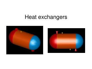
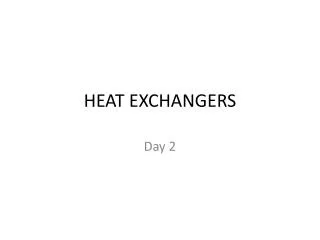
MODULE 7. Introduction to Heat Exchangers. What are heat exchangers for?. Heat exchangers are practical devices used to transfer energy from one fluid to another To get fluid streams to the right temperature for the next process reactions often require feeds at high temp.

Introduction to Heat Exchangers
E N D
Presentation Transcript
MODULE 7 Introduction to Heat Exchangers
What are heat exchangers for? • Heat exchangers are practical devices used to transfer energy from one fluid to another • To get fluid streams to the right temperature for the next process • reactions often require feeds at high temp. • To condense vapours • To evaporate liquids • To recover heat to use elsewhere • To reject low-grade heat • To drive a power cycle
Application: Power cycle Condenser Boiler Feed water Heater Steam Turbine
Main Categories Of Exchanger Heat exchangers Recuperators Regenerators Wall separating streams Direct contact • Most heat exchangers have two streams, hot and cold, but some have more than two
Recuperators/Regenerators • Recuperative: Has separate flow paths for each fluid which flow simultaneously through the exchanger transferring heat between the streams • Regenerative Has a single flow path which the hot and cold fluids alternately pass through.
Compactness • Can be measured by the heat-transfer area per unit volume orby channel size • Conventional exchangers (shell and tube) have channel size of 10 to 30 mm giving about 100m2/m3 • Plate-type exchangers have typically 5mm channel size with more than 200m2/m3 • More compact types available
Double Pipe • Simplest type has one tube inside another - inner tube may have longitudinal fins on the outside • However, most have a number of tubes in the outer tube - can have very many tubes thus becoming a shell-and-tube
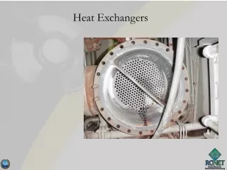
Shell and Tube • Typical shell and tube exchanger as used in the process industry
Plate-Fin Exchanger • Made up of flat plates (parting sheets) and corrugated sheets which form fins • Brazed by heating in vacuum furnace
Heat Transfer Considerations: Overall heat transfer coefficient • Internal and external thermal resistances in series • A is wall total surface area on hot or cold side • R”f is fouling factor (m2K/W) • o is overall surface efficiency (if finned)
Heat Transfer Considerations (contd…): • Fouling factor Material deposits on the surfaces of the heat exchanger tube may add further resistance to heat transfer in addition to those listed above. Such deposits are termed fouling and may significantly affect heat exchanger performance. • Scalingis the most common form of fouling and is associated with inverse solubility salts. Examples of such salts are CaCO3, CaSO4, Ca3(PO4)2, CaSiO3, Ca(OH)2, Mg(OH)2, MgSiO3, Na2SO4, LiSO4, and Li2CO3. • Corrosion fouling is classified as a chemical reaction which involves the heat exchanger tubes. Many metals, copper and aluminum being specific examples, form adherent oxide coatings which serve to passivity the surface and prevent further corrosion.
Heat Transfer Considerations (contd…): • Chemical reaction fouling involves chemical reactions in the process stream which results in deposition of material on the heat exchanger tubes. When food products are involved this may be termed scorching but a wide range of organic materials are subject to similar problems. • Freezing fouling is said to occur when a portion of the hot stream is cooled to near the freezing point for one of its components. This is most notable in refineries where paraffin frequently solidifies from petroleum products at various stages in the refining process, obstructing both flow and heat transfer. • Biological fouling is common where untreated water is used as a coolant stream. Problems range from algae or other microbes to barnacles.
Heat Exchanger Analysis Log mean temperature difference (LMTD) method
Heat Exchanger Analysis (contd…) Energy balance (counterflow) on element shown
Heat Exchanger Analysis (contd…) • Remember – 1 and 2 are ends, not fluids • Same formula for parallel flow (but T’s are different) • Counterflow has highest LMTD, for given T’s therefore smallest area for Q.
Heat Exchanger Analysis (contd…) Evaporator Condenser
Multipass HX Flow Arrangements • In order to increase the surface area for convection relative to the fluid volume, it is common to design for multiple tubes within a single heat exchanger. • With multiple tubes it is possible to arrange to flow so that one region will be in parallel and another portion in counter flow. 1-2 pass heat exchanger, indicating that the shell side fluid passes through the unit once, the tube side twice. By convention the number of shell side passes is always listed first.
Multipass HX Flow Arrangements (contd…) • The LMTD formulas developed earlier are no longer adequate for multipass heat exchangers. Normal practice is to calculate the LMTD for counter flow, LMTDcf, and to apply a correction factor, FT, such that • The correction factors, FT, can be found theoretically and presented in analytical form. The equation given below has been shown to be accurate for any arrangement having 2, 4, 6, .....,2n tube passes per shell pass to within 2%.
Multipass HX Flow Arrangements (contd…) T,t = Shell / tube side; 1, 2 = inlet / outlet
Charts for each Configuration Procedure: Determine Cmax, Cmin/Cmax Get UA/Cmin, from chart
Effectiveness-NTU Method(contd…) • NTUmax can be obtained from figures in textbooks/handbooks • First, however, we must determine which fluid has Cmin