Download
1 / 22
220 likes | 349 Vues
This project, conducted by a team from the University of Idaho, explores innovative solutions for replacing traditional Uninterruptible Power Supplies (UPS) on the Advanced Electric Ship Demonstrator (AESD), "Sea Jet." The study aims to ensure continuous power supply to auxiliary loads while minimizing acoustic contamination and enhancing battery efficiency. Various designs and trade-offs are assessed, with a final focus on maximizing run time and reducing charging cycles. The results show promising alternatives within budget and feasibility constraints.

E N D
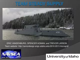
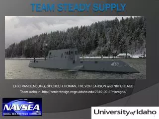
ERIC VANDENBURG, SPENCER HOMAN, TREVOR LARSON and NIK URLAUB Team website: http://seniordesign.engr.uidaho.edu/2010-2011/microgrid/ TEAM STEADY SUPPLY
Table of contents: • Background • Problem Definition • Uninterruptible Power Supply (UPS) • Current Design • Design specifications • Load information • Proposed Design # 1 • Constraints • Proposed Design # 2 • Proposed Design # 3 • Ideas • Design Tradeoffs • Budget • Schedule
Background: • Advanced Electric Ship Demonstrator (AESD) also known as “Sea Jet” • 1/4 scale model, Length: 133 feet, Weight: 239,000 lbs, Location: Bayview, Idaho • AESD is used for a variety of different tests and experiments (eg. Acoustic data collection, Hull modification, Motor types) • Propulsion System is powered by 720 12V@40A/Hr Batteries • Auxiliary System is powered by 4 UPS • Shore power, Diesel Engine used for charging
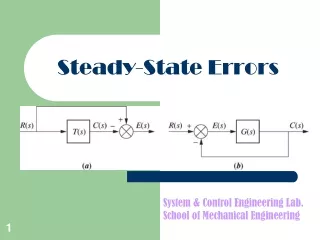
Problem Definition: • This is a Feasibility Study with the following objectives: • Replace the Four Uninterrupted Power Supplies (UPS) • Provide Uninterrupted Power Flow to Every Auxiliary Load. • Increase the Duration of Battery Run Time (Increase Quiet Mode Run time) • Decrease Charge Time for Batteries (Decrease Time Between Quiet Mode Runs) • Decrease Acoustic Contamination
What is an uninterruptible power supply (UPS): • PROS • UPS provide a Load with power at all times • During connection to Shore/Diesel Generator, Load is powered and battery is charging. • During Quiet Mode Runs the Battery supplies the Load with power • CONS • UPS are not designed to run on the internal batteries for extended time • UPS are not designed to charge quickly • UPS are not designed to minimize acoustics (Inverters) • 4 UPS = 4 Inverters = Loud SHORT QUIET MODE RUNS LONG CHARGE TIME ACOUSTIC CONTAMINATION
Design specifications: • Continuous power supply to the loads at all times. • Draw power from a common bus. • Batteries capable of providing power for more than 45 minutes. • Remove the (4) uninterruptible power supplies (UPS) causing unwanted acoustics
Design process: • Brainstormed/researched DC microgrids • Obtained load profiles from NAVSEA • Calculated power consumed by the auxiliary power system • Determined the number of batteries needed. • Would it be feasible to run auxiliary loads off of the propulsion system.
Load information: With Onboard Data Acquisition System (ODAS) equipment off: • UPS #1 – 6.0A • UPS #2 – 13.9A • UPS #3 – 2.0A • UPS #4 – 3.3A With ODAS equipment on: • UPS #1 – 17.4A • UPS #2 – 18.5A • UPS #3 – 7.3A • UPS #4 – 3.3A UPS #4 has weak batteries causing ODAS configuration not to be utilized for this unit.
Design Schematic# 1 Estimated run time: 46.997 minutes
Constraints: • Space: Current UPS dimensions 4*(4ft. by 2ft. by 2ft.). Battery dimensions 24*(12 in. by 6 in. by 4 in.) SPACE not a problem. • Cost: Compare each design (Comparison in tradeoff Table)
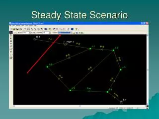
Design Schematic # 2 • Auxiliary System ties into one battery string of the Propulsion System • Auxiliary load is roughly only 12% of Propulsion load. Propulsion System will be able to support auxiliary system. • Vital Loads have power at all times • Estimated run time: • 1 Hour 45 minutes
Design Schematic # 3 • Auxiliary System ties into all 6 battery strings of the Propulsion System • Auxiliary load is roughly only 1% of Propulsion load. Propulsion System will be able to support auxiliary system. • Vital Loads have power at all times • Estimated run time: • 21.399 Hours
Options Considered • Current Lead-Acid Batteries (12V @ 40A/Hr) • Lithium-Ion Batteries (36.8V @ 50A/Hr) • Fuel cells (not feasible) • Size needed for storage • cost • Back up battery bank for Design # 2 • Types of Inverters, most cost effective and easy to implement
Project Learning • Gained knowledge of DC microgrids • A better understanding of one-line diagrams • Basic battery bank design • Better team communication • Site visit • The operations and uses of the AESD
Budget: • Site Visit (2): $308.80 • Poster: $75.00 • Total: $383.80
Schedule: • Start of Semester: January 10, 2011 • Detailed Design Review: February 15,2011 • Snapshot Day: March 8, 2011 • Expo: April 29, 2011 • Logbooks Due: May 5, 2011 • Final Report: May 5, 2011