Optimizing DC Spark System Anode Tip Design for Enhanced Capacitance and Alignment Sensitivity
140 likes | 247 Vues
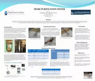
This study explores a newly designed anode tip for the DC spark system, addressing issues with previous tips, such as low capacitance and sensitivity to angular misalignments. By optimizing the radius of the anode tip and curvature angle, we aim to create a design that achieves maximum capacitance while maintaining stability under misalignment conditions. Using simulation software and analytical models, we determine the optimal parameters, ultimately suggesting an ideal tip geometry that balances capacitance and alignment tolerance necessary for effective experimentation.

Optimizing DC Spark System Anode Tip Design for Enhanced Capacitance and Alignment Sensitivity
E N D
Presentation Transcript
A new anode tip for the DC spark system Robin Rajamäki 1.7.2014
Problem definition • Gap distance measured through capacitance in system 1 • Problems with previous tips: • Capacitance too low (hemispherical tip) • Sensitivity to small angular misalignments (flat tip) Need a compromise between a large capacitance and a small sensitivity to angular misalignment.
Approach • Parameters: • R = radius of anode tip • r = radius of curvature • α= angle of curvature • h = height of anode tip • Design criteria: • ”Need 2-3 spots on the cathode surface for experiments”
Approach • Design constraints: • Field drops (at least) 50 % 2 mm away from the point where the A and the C are closest to eachother • Field within 2 mm region remains unchanged for 10 deg misalignment • Goal: • Find R and r that satisfy the above constraints and maximize the capacitance!
Approach • Motivation for choosing 10 degrees Note the the anode is untypically misaligned here!
Methods • Find R= f(α) for which the geometry within the critical region remains unchanged at a maximal misalignment of θ (constraint 2) • Find R_opt = f(α_opt), which gives E(x = 2mm) = E0/2 (constraint 1) R_opt, α_opt will maximize the capacitance and meet the design constraints.
Method • Tools: • Simulation software • FEM modeling in Ansys Maxwell v. 15 • Data analysis in Matlab • Analytical models • Sphere close to infinite plate • Parallel plate capacitor • Used to approximate upper bounds of numerical simulations
Results • Solution boundaries Boundaries of interest
Results • Function satisfying constraint 2: R = f(α) = ,
Results • Electric field magnitude at x = 2 mm for R(α) R ≈ 20 mm
Results • Capacitance and change in capacitance for R(α)
Discussion • Optimal tip: • R ≈ 20 mm • α ≈ 23⁰ • 4 cm diameter may be impractically large... ... decrease R (= increase α) whilst keeping acceptible C and ΔC.
Discussion • Alternative tip: d = 1.3 mm, h = 1 mm
Discussion • Solution visualisation