Download

1 / 31
310 likes | 389 Vues
Learn the step-by-step design process of combinational circuits using truth tables, Boolean expressions, logic diagrams, and verification methods. Explore Half Adders, Full Adders, Subtractors, Multiplexers, Demultiplexers, Encoders, Decoders, and Comparators with examples.

E N D
Combinational Circuit Design Presented by K. Pandiaraj Assistant Professor ECE Kalasalingam University
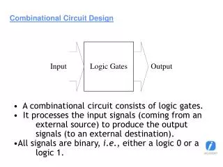
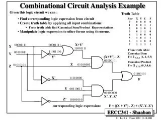
Combinational Circuit Design Design Procedure: Determine required number of inputs and outputs from the specifications. Derive the truth table for each of the outputs based on their relationships to the input. Simplify the Boolean expression for each output. Use Karnaugh Maps or Boolean algebra. Draw a logic diagram that represents the simplified Boolean expression. Verify the design by analysing or simulating the circuit.
Half Subtractor • Half Subtractor is used for subtracting one single bit binary digit from another single bit binary digit. The truth table of Half Subtractor is shown below.
Multiplexers • A multiplexer has • N control inputs • 2N data inputs • 1 output • A multiplexer routes (or connects) the selected data input to the output. • The value of the control inputs determines the data input that is selected.
Demultiplexers • A demultiplexer has • N control inputs • 1 data input • 2N outputs • A demultiplexer routes (or connects) the data input to the selected output. • The value of the control inputs determines the output that is selected. • A demultiplexer performs the opposite function of a multiplexer.
W W = A'.B'.I Out0 X Out1 X = A.B'.I I In Y Out2 Y = A'.B.I Z Out3 S1 S0 Z = A.B.I A B Demultiplexers
Decoders • A decoder has • N inputs • 2N outputs • A decoder selects one of 2N outputs by decoding the binary value on the N inputs. • The decoder generates all of the minterms of the N input variables. • Exactly one output will be active for each combination of the inputs.
W = A'.B' W Out0 X = A.B' B I0 X Out1 Y A Out2 I1 Y = A'.B Z Out3 Z = A.B Decoders msb Active-high outputs
W = (A'.B')' W Out0 X = (A.B')' B I0 X Out1 Y A Out2 I1 Y = (A'.B)' Z Out3 Z = (A.B)' Decoders msb Active-low outputs
Decoders msb
W Out0 B I0 X high-level enable Out1 A I1 Y Out2 Z Out3 Enable En Decoder with Enable enabled disabled
W Out0 B I0 X low-level enable Out1 A I1 Y Out2 Z Out3 Enable En Decoder with Enable enabled disabled
Encoders • An encoder has • 2N inputs • N outputs • An encoder outputs the binary value of the selected (or active) input. • An encoder performs the inverse operation of a decoder. • Issues • What if more than one input is active? • What if no inputs are active?
Encoders D I0 Z Out0 C I1 Out1 Y B I2 A I3
Priority Encoders • If more than one input is active, the higher-order input has priority over the lower-order input. • The higher value is encoded on the output • A valid indicator, d, is included to indicate whether or not the output is valid. • Output is invalid when no inputs are active • d = 0 • Output is valid when at least one input is active • d = 1
Priority Encoders msb Valid bit
Digital Comparator • A magnitude digital comparator is a combinational circuit that compares two digital or binary numbers (consider A and B) and determines their relative magnitudes in order to find out whether one number is equal, less than or greater than the other digital number. • Three binary variables are used to indicate the outcome of the comparison as A>B, A<B, or A=B. The below figure shows the block diagram of a n-bit comparator which compares the two numbers of n-bit length and generates their relation between themselves.