Download
1 / 46
480 likes | 521 Vues
This overview covers the challenges and properties of carbon nanotubes in space elevator construction. It discusses elevator construction, challenges faced, potential issues, and health hazards. Additionally, it delves into the properties of CNTs, including synthesis techniques, growth mechanisms, and their applications in electronics and sensors. The text elaborates on scalability, sensing mechanisms, and nanotube formation. The anchor station, catalysts, and SWNTs' characteristics are also explored.

E N D
CNTs David Shaw EE
Proposed System: Overview • First elevator: 20 ton capacity (13 ton payload) • Constructed with existing or near-term technology
Challenges • Induced Currents: milliwatts and not a problem • Induced oscillations: 7 hour natural frequency couples poorly with moon and sun, active damping with anchor • Radiation: carbon fiber composites good for 1000(?) years in Earth orbit (LDEF) • Atomic oxygen protecyion: <25 micron Nickel coating between 60 and 800 km • Environmental Impact: Ionosphere discharging not an issue(?) • Malfunctioning climbers: up to 3000 km reel in the cable, above 2600 km send up an empty climber to retrieve the first • Lightning, wind, clouds: avoid through proper anchor location selection • Meteors: ribbon design allows for 200 year probability-based life • Health hazards: under investigation but initial tests indicate minimal problem • Damaged or severed ribbons: collatoral damage is minimal due to mass and distribution
Anchor • Anchor station is a mobile, ocean-going platform identical to ones used in oil drilling • Anchor is located in eastern equatorial pacific, weather and mobility are primary factors
Discharges • Cheap • Yield ~30% • Short (<50 microns) • Random deposits
Catalytic CVD Growth Hongjie Dai, Stanford
Catalytic Methods • High potential for scale-up production • Long lengths • Multiwall CNTs • Many defects in the materials
Laser Ablation • High (~70%) yield single- wall CNTs • High costs
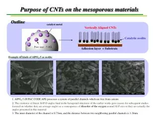
Scanning electron microscopy images of raw (on the left) and purified (on the right) SWNTs
CNT for electronics • Carrier transport is 1-D. • All chemical bonds are satisfied CNT Electronics not bound to use SiO2 as an insulator. • High mechanical and thermal stability and resistance to electromigration Current densities up to 109 A/cm2 can be sustained. • Diameter controlled by chemistry, not fabrication. • Both active devices and interconnects can be made from semiconducting and metallic nanotubes.
Conductivity Change of CNTs Upon Gas/Vapor Adsorption Courtesy of M. Meyyappan • Early chemical sensors were of the CHEMFET type with SnO2 and other oxide conducting channels • Similar CNT-FETs have been tested in the literature, exposing to NH3, NO2, etc.; change in conductivity has been observed • Limitations of CNT-FET - Single SWCNT is hard to transfer or grow in situ - Even a film of SWCNTs by controlled deposition in the channel is complex - 3-terminal device is complex to fabricate - Commercial sensor market is very cost sensitive
By the courtesy of Dr. M. Meyyappan @ NASA Ames Research Center Nanosensing Technology A relative resistance or current is measured from each sensor • Operation: • The relative change of current or resistance is correlated to the concentration of analyte. • Array device “learns” the response pattern in the training mode. • Unknowns are then classified in the identification mode. Using pattern matching algorithms, the data is converted into a unique response pattern
Scalable Array Approach (Multi-channel Sensing Chip) Courtesy of M. Meyyappan • 12 to 36 sensing elements are on a chip (1cm x 1cm) now with heaters and thermistors. • Number of sensing elements can be increased on a chip. • Number of chips can be increased on a 4” wafer. • Wafer size can be increased to 6”, 8”, or 12”. • SWCNT solution-casting by ink jetting or using microarrays
O=N=O CH3 NO2 O=N=O . e CH3 P-type O=N=O E0 EC EF EV e e SWCNT Intratube Modulation Intertube Modulation Sensing Mechanisms Courtesy of M. Meyyappan Nitrotoluene
The insertion of a pentagon into the wall structure initiates tapering in the nanotube wall.
Why do Carbon Nanotubes form? Carbon Graphite (Ambient conditions) sp2 hybridization: planar Diamond (High temperature and pressure) sp3 hybridization: cubic Nanotube/Fullerene (certain growth conditions) sp2 + sp3 character: cylindrical Finite size of graphene layer has dangling bonds. These dangling bonds correspond to high energy states. Eliminates dangling bonds Nanotube formation + Total Energy Increases Strain Energy decreases