Key Concepts Sinusoids and Phasors Phasor circuit analysis
430 likes | 787 Vues
Key Concepts Sinusoids and Phasors Phasor circuit analysis Basic phasor circuit analysis and design Circuit theorems with phasors General circuit analysis with phasors Energy and power. Keywords Phasor Phasor representation Rotating phasor Additive property In phase Out of phase

Key Concepts Sinusoids and Phasors Phasor circuit analysis
E N D
Presentation Transcript
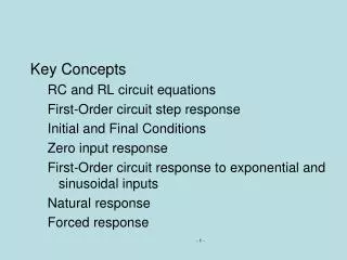
Key Concepts Sinusoids and Phasors Phasor circuit analysis Basic phasor circuit analysis and design Circuit theorems with phasors General circuit analysis with phasors Energy and power
Keywords Phasor Phasor representation Rotating phasor Additive property In phase Out of phase Resonant frequency Phasor domain Resistance – reactance Admittance Susceptance Conductance Low pass filter Bandpass filter Cutoff frequency Proportionality Superposition Source transformation Planar circuits Conjugate match
Reading The Analysis & Design of Linear Circuits Sections 8-1 to 8-6 Pages 379-446
Sinusoids and Phasors Phasor Review When working with phasors – we work with complex numbers Mathematicians use the symbol i for imaginary numbers Electrical engineers reserve i for current so we use the symbol j Addition and subtraction are easiest in the rectangular system Multiplication and division etc. are easiest in the polar system
Sinusoids and Phasors Phasor Review Simplifying a complex relation
Sinusoids and Phasors Phasor Review A phasor can be represented in either polar …. ….or in rectangular form
Sinusoids and Phasors Phasor Review Phasors can be manipulated mathematically V1=20 + j20 V3= V1 + V2 They can also be viewed graphically
Sinusoids and Phasors Phasor Review The i-v equations for R, L, and C can be expressed in phasor form become or
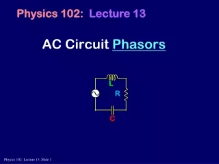
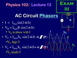
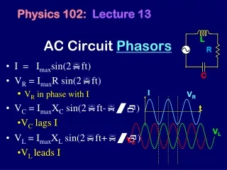
Sinusoids and Phasors Phasor Review Leading or Lagging Current and Voltage R Both are in phase – no leading or lagging L The voltage phasor leads the current phasor by 90o C The voltage phasor lags the current phasor by 90o
Sinusoids and Phasors Phasor Review Z is a complex number it can be written as R is the real part and is called resistance X is the imaginary part and is called reactance R can only be positive X can be either positive or negative When it is positive it is called inductive reactance When negative capacitive reactance
Sinusoids and Phasors Phasor Review Find ZEQ for the following circuit
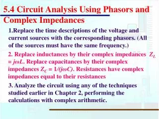
Sinusoids and Phasors Basic Phasor Circuit Analysis Frequency and Impedance
Sinusoids and Phasors Basic Phasor Circuit Analysis
Sinusoids and Phasors Basic Phasor Circuit Analysis
Sinusoids and Phasors Basic Phasor Circuit Analysis
Sinusoids and Phasors Nodal Analysis Energy and Power Node Voltage equations remain the same but substitute a Z in place of an R
Sinusoids and Phasors Nodal Analysis
Sinusoids and Phasors Nodal Analysis - Active Circuits
Sinusoids and Phasors Energy and Power Find the average power delivered to the load Find the maximum available average power at the interface Specify the load required to extract the maximum average power
Sinusoids and Phasors Energy and Power Use node-voltage analysis to find the average power delivered to the load VA = 21.6 ‒ j28.8 V Then we find ILOAD= VA/(1500) Finally, PLOAD = 500 | ILOAD |2/2 = 144 mW To find the maximum available average power, we need to find the Thévenin equivalent for the source.
Sinusoids and Phasors Energy and Power To find the maximum available average power…find the Thévenin equivalent for the source V T = 60 ∟0o Z T = 1KΩ + j2 KΩ To achieve the maximum power delivered to the load, the load impedance must be the complex conjugate of the Thévenin impedance.
Key Concepts Laplace transform Inverse Laplace transform Integration property Differentiation property s-Domain translation property time-Domain translation property Signal waveforms and transforms Basic properties and pairs Pole-Zero diagrams Circuit response using Laplace transforms Initial and final value properties
Keywords Waveform Transform Transform pair Piecewise continuous Exponential order Uniqueness property Poles Zeros Critical frequencies Rational functions Proper rational functions Improper rational function • Partial fraction expansion • Uniqueness property • Simple poles • Complex poles • Residues
Reading The Analysis & Design of Linear Circuits Sections 9-1 to 9-4 Pages 447-479
Laplace Transforms and Inverse Laplace Transforms Laplace Transforms The single-sided Laplace transform is defined as…
Laplace Transforms and Inverse Laplace Transforms Laplace Transforms When working with the Laplace transform Integration in the s-domain is division of the transform by s Differentiation in the s-domain is multiplication by s, but there is a need to include initial conditions
Laplace Transforms and Inverse Laplace Transforms Laplace Transforms The inverse Laplace transform is defined as…
Laplace Transforms and Inverse Laplace Transforms Laplace Transforms The uniqueness property of the Laplace transform states… If the L{f(t)}= F(s), then L-1 {F(s)}=f(t) Thus… Taking the Laplace transform of v(t) v(t) = 10 e–100tu(t) → V(s) = 10/(s+100). Then the inverse L-1 of V(s) is V(s) = 10/(s+100) → v(t) = 10 e–100tu(t).
Laplace Transforms and Inverse Laplace Transforms Laplace Transforms The Laplace transform of f(t) = 10[e50t - 2e100 t ] u(t). The poles and zeros of F(s) are located at The poles are s = −50 and s = −100. The zero is s = 0
Pole Zero Diagrams and Inverse Laplace Transforms Introduction to Pole Zero Diagrams The zeros of a Laplace function make the numerator go to zero The poles of a Laplace function make the denominator go to zero The zeros are plotted with a small o The poles are plotted with a small x
Pole Zero Diagrams and Inverse Laplace Transforms Introduction to Pole Zero Diagrams Before we can construct a pole-zero plot we do a partial fraction expansion There are four types of partial fraction expansion Simple Real Poles Simple Complex Poles Improper Fractions Multiple Poles
Pole Zero Diagrams and Inverse Laplace Transforms Introduction to Pole Zero Diagrams Simple Real Poles becomes
Pole Zero Diagrams and Inverse Laplace Transforms Introduction to Pole Zero Diagrams Simple Complex Poles becomes
Pole Zero Diagrams and Inverse Laplace Transforms Introduction to Pole Zero Diagrams Improper Fractions becomes
Pole Zero Diagrams and Inverse Laplace Transforms Introduction to Pole Zero Diagrams Multiple Poles becomes
Initial and Final Value Theorems Applying the Initial and Final Value Theorems Find the differential equation for the IL(t) and its initial value IL(0)
Initial and Final Value Theorems Applying the Initial and Final Value Theorems Transform the voltage source Write the differential equation with initial condition
Initial and Final Value Theorems Applying the Initial and Final Value Theorems The initial and final value theorems are easy to use They do not apply under the following conditions… Final Value, Poles on the imaginary axis or on the RHP – except one pole at the origin is OK; Initial Value No impulses at 0).
Initial and Final Value Theorems Applying the Initial and Final Value Theorems Find the initial and final values of the waveforms corresponding to the transforms f1(0) = 0 and f1(∞) = 0 f2(0) = 0 and f2(∞) = 0.002
Initial and Final Value Theorems Applying the Initial and Final Value Theorems Find the initial and final values of the waveforms corresponding to the transforms f3(0) = 0 and f1(∞) = 0 f4(0) = 3 and f2(∞) does not exist, because sF4(s) has poles with non-negative real parts
SUMMARY: In this unit, we first presented with a review of basic phasors and their use as a powerful analysis tool for circuits with sinusoidal inputs then a short discussion of energy and power transfer. In the second part of the unit, we introduced the Laplace transform, the inverse transform, and pole-zero plots as tools that supported easy movement between the time and frequency domains.
REMINDERS: Assignments from Unit 5 are due at start of next unit. Prepare for the next unit by reading: Thomas, Rosa, and Toussaint, Sections 10-1 to 10-6 and 11-1. 11-2, and 11-7, prior to coming to class.