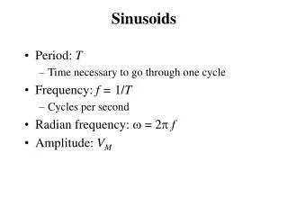
Chapter 9 Sinusoids and Phasors
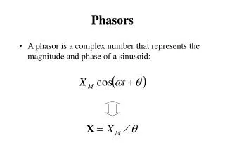
Phasor Relationships for circuit Elements. Impedance and Admittance. Kirchoff’s Laws in the Frequency Domain. Impedance Combinations. Applications. Chapter 9 Sinusoids and Phasors.

Chapter 9 Sinusoids and Phasors
E N D
Presentation Transcript
Phasor Relationships for circuit Elements. Impedance and Admittance. Kirchoff’s Laws in the Frequency Domain. Impedance Combinations. Applications. Chapter 9Sinusoids and Phasors Huseyin BilgekulEENG224 Circuit Theory IIDepartment of Electrical and Electronic EngineeringEastern Mediterranean University
Phasor Relationships for Circuit Elements • After we know how to convert RLC components from time to phasor domain, we can transform a time domain circuit into a phasor/frequency domain circuit. • Hence, we can apply the KCL laws and other theorems to directly set up phasor equations involving our target variable(s) for solving. • Next we find the phasor or frequency domain equivalent of the element equations for RLC elements.
Phasor Relationships for Circuit Elements Phasor voltage and current of a resistor are in phase Time Domain Frequency Domain
Phasor Relationship for Resistor Frequency Domain Time Domain Voltage and current of a resistor are in phase
Phasor Relationships for Inductor Phasor current of an inductor LAGS the voltage by 90 degrees. Time Domain Frequency Domain
Phasor Relationships for Inductor Phasor current of an inductor LAGS the voltage by 90 degrees. Frequency Domain Time Domain
Phasor Relationships for Capacitor Phasor current of a capacitor LEADS the voltage by 90 degrees. Time Domain Frequency Domain
Phasor Relationships for Capacitor Phasor current of a capacitor LEADS the voltage by 90 degrees. Frequency Domain Time Domain
Impedance and Admittance • The Impedance Z of a circuit is the ratio of phasor voltage V to the phasor current I. • The Admitance Y of a circuit is the reciprocal of impedance measured in Simens (S). • Impedances and Admitances of passive elements.
Impedance as a Function of Frequency • The Impedance Z of a circuit is a function of the frequency. • Inductor is SHORT CIRCUIT at DC and OPEN CIRCUIT at high frequencies. Capacitor is OPEN CIRCUIT at DC and SHORT CIRCUIT at high frequencies.
+ V - Z I Impedance of Joint Elements • The Impedance Z represents the opposition of the circuit to the flow of sinusoidal current. • The Reactance is Inductive if X is positive and it is Capacitive if X is negative.
Impedance as a Function of Frequency • As the applied frequency increases, the resistance of a resistor remains constant, the reactance of an inductor increases linearly, and the reactance of a capacitor decreases nonlinearly. Reactance of inductor versus frequency Reactance of capacitor versus frequency
Admittance of Joint Elements • The Admittance Y represents the admittance of the circuit to the flow of sinusoidal current.The admittance is measured in Siemens (s) + V - Y I
Application of KVL for Phasors • The Kirchoff”s Voltage Law (KVL) holds in the frequency domain. For series connected impedances: • The Voltage Division for two elements in series is:
Parallel Combination for Phasors • The Kirchoff”s Voltage Law (KVL) holds in the frequency domain. For series connected impedances: • The Current Division for two elements is:
Z3 Z1