Data Conversion & Integration
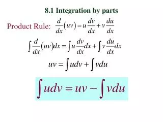
Data Conversion & Integration. Data Conversion/Integration Process. Data Collection Existing hard-copy maps / digital data Satellite Imagery, Aerial Photo, etc. Field Collection (hand-held devices-GPS, etc.) Data Input/Conversion Keyboard entry of coordinates

Data Conversion & Integration
E N D
Presentation Transcript
Data Conversion/Integration Process • Data Collection • Existing hard-copy maps / digital data • Satellite Imagery, Aerial Photo, etc. • Field Collection (hand-held devices-GPS, etc.) • Data Input/Conversion • Keyboard entry of coordinates • Digitizing/Scanning/Raster-to-Vector • Editing/Building Topology • Data Integration • Georeferencing
Data sources for EA mapping • Types of maps required • Inventory of existing sources • Importing existing digital data • Additional geographic data collection • Traditional field techniques • Aerial photography • Remote sensing • Satellite remote sensing • GPS
Why Data Inventory? • Identify existing data sources • Up to 70% of GIS projects • Geographic data: Labor intensive, tedious and error-prone
Inventory of existing Hard copy maps • National overview maps 1:250,000-1:5,000,000 (small scale) • show major civil divisions, urban areas, physical features such as roads, rivers, lakes, elevation, etc. • used for planning purposes • Topographic maps- scales range from 1:25,000 to 250,000 (mid-scale) • Town and city maps at large cartographic scales, showing roads, city blocks, parks, etc. (1:1,000 to 1:5,000) • Maps of administrative units at all levels of civil division • Thematic maps showing population distribution for previous census dates, or any features that may be useful for census mapping
Existing Digital Data • Direct import of: • Digital maps • Air photos • Satellite imagery • Etc.
Additional Data Collection Capture Aerial Photography Remote Sensing Surveying. GPS Maps GDB Census & Surveys GIS Management
Aerial photography • Aerial photography is obtained using specialized cameras on-board low-flying planes. The camera captures the image digitally or on photographic film. • Aerial photography is the method of choice for mapping applications that require high accuracy and a fast completion of the tasks. • Photogrammetry—the science of obtaining measurements from photographic images.
Aerial photography (cont.) • Traditional end product: printed photos • Digital image (scanned from photo) in standard graphics format (TIFF, JPEG) that can be integrated in a GIS or desktop mapping package • Trend: fully digital process • digital orthophotos • corrected for camera angle, atmospheric distortions and terrain elevation • georeferenced in a standard projection (e.g. UTM) • geometric accuracy of a topographic map • large detail of a photograph
Remote sensing process Receiving station
GPS • Collection of point data • Stored as “waypoints” • Accuracy dependent on device and environmental variables Surveying • Paper Based • Manual recording of information • Electronic Based • Handheld device
Geographic data input/conversion • Keyboard entry of coordinates • Digitizing • Scanning and raster to vector conversion • Field work data collection using • Global positioning systems • Air photos and remote sensing
Keyboard entry • keyboard entry of coordinate data • e.g., point lat/long coordinates • from a gazetteer (a listing of place names and their coordinates) • from locations recorded on a map
Latitude/Longitude coordinate conversion • Latitude is y-coo, Longitude is x-coo • Common format is degrees, minutes, seconds 113º 15’ 23” W 21º 56’ 07” N • To represent lat/long in a GIS, we need to convert to decimal degrees -113.25639 21.93528 • DD = D + (M + S / 60) / 60
Conversion of hardcopy maps to digital data • Turning features that are visible on a hardcopy map into digital point, line, polygon, and attribute information • In many GIS projects this is the step that requires by far the largest time and resources (Up to 80% of project costs) • Newer methods are arising to minimize this arduous step • Data transfer often rely on the exchange of data in mostly proprietary file formats using the import/export functions of commercial GIS packages • Open source data Conversion software becoming widely available
Conversion of hardcopy maps to digital data (cont.) • Digitizing • Manual digitizing • Heads-up digitizing • Scanning • Raster-to-Vector
Conversion of hardcopy maps to digital data (cont.) Digitized or scanned Paper map (static) Digital map (reproduced at will)
Manual Digitizing Most common form of coordinate data input • Requires a digitizing table • Ranging in size (25x25 cm to 150x200cm) • Ideally the map should be flat and not torn or folded • Cost: hundreds to thousands $
Digitizing steps (how points are recorded) • Trace features to be digitized with pointing device (cursor) • Point mode: click at positions where direction changes • Stream mode: digitizer automatically records position at regular intervals or when cursor moved a fixed distance
Heads-Up Digitizing I • Features are traced from a map drawn on a transparent sheet attached to the screen • Option, if no digitizer is available; but: accuracy very low
Heads-Up Digitizing II • Common today is heads-up digitizing, where the operator uses a scanned map, air photo or satellite image as a backdrop and traces features with a mouse • This method yields more accurate results • Quicker and easier to retrace and save steps
Heads-Up Digitizing II • Raster-scanned image on the computer screen • Operator follows lines on-screen in vector mode
Advantages and Disadvantages of Digitizing Advantages • It is easy to learn and thus does not require expensive skilled labor • Attribute information can be added during digitizing process • High accuracy can be achieved through manual digitizing; i.e., there is usually minimal loss of accuracy compared to the source map
…Cont. Disadvantages • It is a tedious activity, possibly leading to operator fatigue and resulting quality problems which may require considerable post-processing • It is slow. Large-scale data conversion projects may thus require a large number of operators and digitizing tables • The accuracy of digitized maps is limited by the quality of the source material
Scanning: A viable alternative to digitizing • Electronic detector moves across map and records light intensity for regularly shaped pixels • Flat-bed scanner • Drum-scanner (pictured)
…Cont. • direct use of scanned images • e.g., scanned air-photos • digital topographic maps in raster format • Scanner output is a raster data set usually needs to be converted into a vector representation • Often requires considerable editing
Advantages and Disadvantages of Scanning Advantages: • Scanned maps can be used as image backdrops for vector information • Scanned topographic maps can be used in combination with digitized EA boundaries for the production of enumerator maps • Small-format scanners are relatively inexpensive and provide quick data capture
…Cont. Disadvantages: • Converting large maps with a small format scanners requires tedious re-assembly of the individual parts • Large format, high-throughput scanners are expensive • Despite recent advances in vectorization software associated with scanning, considerable manual editing and attribute labeling may still be required
Raster to Vector Conversion Gets scanned/image data into vector format • Automatic mode: the system converts all lines on the raster image into sequences of coordinates automatically. automated raster to vector process starts with a line thinning algorithm • Semi-automatic mode, the operator clicks on each line that needs to be converted; system then traces that line to the nearest intersections and converts it into a vector representation
Editing • Manual digitizing is error prone • Objective is to produce an accurate representation of the original map data • This means that all lines that connect on the map must also connect in the digital database • There should be no missing features and no duplicate lines • The most common types of errors • Reconnect disconnected line segments, etc
Digitizing errors • Any digitized map requires considerable post-processing • Check for missing features • Connect lines • Remove spurious polygons • Some of these steps can be automated
Fixing Errors • Some of the common digitizing errors shown in the figure can be avoided by using the digitizing software’s snap tolerances that are defined by the user • For example, the user might specify that all endpoints of a line that are closer than 1 mm from another line will automatically be connected (snapped) to that line • Small sliver polygons that are created when a line is digitized twice can also be automatically removed
Building Topology • GIS determines relationships between features in the database • System will determine intersections between two or more roads and will create nodes • For polygon data, the system will determine which lines define the border of each polygon • After the completed digital database has been verified to be error-free • The final step is adding additional attributes
Converting Between Different Digital Formats • All software systems provide links to other formats • But the number and functionality of import routines varies between packages • Problems often occur because software developers are reluctant to publish the exact file formats that their systems use • Option of using a third data format • Example: Autocad’s DXF format
Integrating data • Georeferencing • Converting map coordinates to the real world coordinates corresponding to the source map’s cartographic projection (or at digitizing stage). • Attaching codes to the digitized features • Integrating attribute data • Spreadsheets • links to external database
Summary • Data conversion • Conversion of hard-copy maps to digital maps • Digitizing • Scanning • Editing • Building Topology • Data integration • Geo-referencing • Projection change • Coding • Integration of attribute data
Geographical Data Accuracy • Logical accuracy • Refers to the integrity of relationships among geographic features • e.g. a river stored in a hydrological database that defines the boundary between admin. Units should coincide with the boundary between those units • Positional accuracy • Coordinates of features in the GIS database are correct relative to their true position on the earth’s surface. • Note: For a census database, it may be more important that a certain street defines the boundary of an EA, than to know that the exact coordinates represent the real-world
Agencies to contact • National geographic institute / mapping agency • Military mapping services • Province, district and municipal governments • Various government or private organizations dealing with spatial data • Geological or hydrological survey • Environmental protection authority • Transport authority • Utility and communication sector companies • Land titling & surveying agencies • Academic institutions • Donor activities
Resolution Data resolution: Typically applied to raster GIS databases, this is the size of raster grid cells. Resolution is the measurement of the smallest map feature that can be stored or displayed
OBIA Raster to Vector Conversion • Object-Based Image Analysis (OBIA) is a tentative name for a sub-discipline of GIScience devoted to partitioning remote sensing (RS) imagery into meaningful image-objects, and assessing their characteristics through spatial, spectral and temporal scale. At its most fundamental level, OBIA requires image segmentation, • attribution, classification and the ability to query and link individual objects (a.k.a. segments) in space and time. In order to achieve this, OBIA incorporates knowledge from a vast array of disciplines involved in the generation and use of geographic information (GI).
OBIA Dwelling Identification • Segmentation based • Pixel based • Automated Digitizing
Object-Based Image Analysis • Increasing demand for updated geo-spatial information, rapid information extraction • Complex image content of VHSR data needs to be structured and understood • Huge amount of data can only be utilized by automated analysis and interpretation • New target classes and high variety of instances • Monitoring systems and update cycles • Transferability, objectivity, transparency, flexibility