Spintronics with topological insulator
Spintronics with topological insulator. Takehito Yokoyama, Yukio Tanaka * , and Naoto Nagaosa Department of Applied Physics, University of Tokyo, Japan * Department of Applied Physics, Nagoya University, Japan. arXiv:0907.2810. Edge state s. From http://www.physics.upenn.edu/~kane/.

Spintronics with topological insulator
E N D
Presentation Transcript
Spintronics with topological insulator Takehito Yokoyama, Yukio Tanaka*, and Naoto Nagaosa Department of Applied Physics, University of Tokyo, Japan *Department of Applied Physics, Nagoya University, Japan arXiv:0907.2810
Edge states From http://www.physics.upenn.edu/~kane/
Quantum Spin Hall state Kane and Mele PRL 2005 B. A. Bernevig and S.-C. ZhangPRL2006 • Spin filtered edge states • One to one correspondence between spin and momentum Fu, Kane & Mele PRL 07 Moore & Balents PRB 07 Roy, cond-mat 06 • Generalization of quantum Spin Hall state to 3D
3D Topological insulator Bi1-xSbx Observation of Dirac dispersion! D. Hsieh et al. Nature (2008) & Science (2009)
Motivation In topological insulator, electrons obey Dirac equation 1.This corresponds to the infinite mass Rashba model 2.Zeeman field acts like vector potential Therefore, spintronics on topological insulator seems promising! We study magnetotransport on topological insulator.
Setup Current
Formalism Hamiltonian Wavefunctions Boundary condition gives Conductance Fermi energy
Magnetoresistance • Polar angle of F1 Azimuthal angle of F1
Magnetoresistance in pn junction • Polar angle of F1 Azimuthal angle of F1
Continuity of wavefunction Parallel configuration Anti-parallel configuration Band gap nn junction F1 F2 F1 F2 F1 F1 Fermi level Fermi level pn junction F2 F2
Inclusion of barrier region Due to mismatch effect, some barrier region may be formed near the interface. We find that transmission coefficient is π-periodic with respect to Z This indicates spin rotation through the barrier
Magnetoresistance in pn junction Opposite tendency due to spin rotation through the barrier region
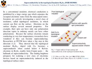
Discussion Typical value of induced exchange field due to the magnetic proximity effect would be 5∼50 meV (from experiments in graphene and superconductor) H. Haugen,et al, Phys. Rev. B 77, 115406 (2008). J. Chakhalianet al., Nat. Physics 2, 244 (2006). E can be tuned by gate electrode or doping below the bulk energy gap (∼ 100 meV) Ferromagnet breaks TRS, which would tame the robustness against disoder. However, high quality topological insulator can be fabricated Fermi velocity Mean free path Y. S. Hor et al., arXiv:0903.4406v2 Localization does not occur and surface state is stable for exchange field smaller than the bulk energy gap The characteristic length of the wavefuction Thomas-Fermi screening length Thus, we have for for Bi2Se3 H. Zhang et. al, Nat. Phys. 5, 438 (2009).
Conclusion We investigated charge transport in two-dimensional ferromagnet/feromagnet junction on a topological insulator. The conductance across the interface depends sensitively on the directions of the magnetizations of the two ferromagnets, showing anomalous behaviors compared with the conventional spin-valve. The conductance depends strongly on the in-plane direction of the magnetization. The conductance at the parallel configuration can be much smaller than that at the antiparallel configuration. • This stems from the connectivity of wavefunctions between both sides.
Overlap integral Incident wavefunction Transmitted wavefunction nn junction pn junction